Machine tool electrical equipment fault diagnosis method - Database & Sql Blog Articles
There are many methods for repairing electrical faults of machine tools, such as voltage method, resistance method and short circuit method.
(1) Voltage measurement method: refers to a method of measuring the range of fault points or faulty components by measuring the voltage value between two points on the electrical line of the machine tool by using a multimeter.
Figure 2-9 Step-by-step measurement of voltage 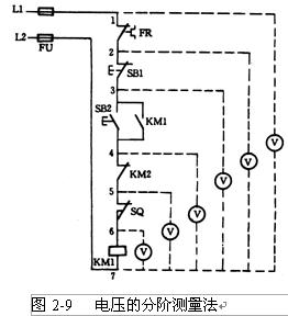
The step-by-step measurement of the voltage of the 1st order measurement method is shown in Figure 2-9.
When inspecting, first measure the voltage between 1 and 7 with a multimeter. If the circuit is normal, it should be 380V. Then press and hold the start button SB2, and connect the black watch bar to the point 7, and the red watch bar moves forward in the order of 6, 5, 4, 3, 2, respectively, measuring 7-6, 7-5, 7 respectively. -4, 7-3, 7-2 The voltage between the various steps, under normal conditions, the voltage value of each step is 380V. If there is no voltage between 7-6, it means that it is an open circuit fault. At this time, the red watch rod can be moved forward. When moving to a certain point (such as 2 points), the voltage is normal, indicating the contact or wiring before point 2. There is a broken circuit. It is usually the first contact after point 2 (ie the contact of stop button SB1 just crossed) or the connection line is open.
Figure 2-10 Sectional measurement of voltage 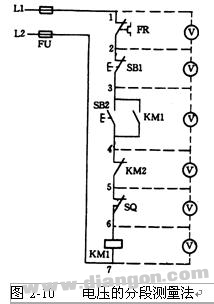
The segmentation measurement method of the 2-segment measurement voltage is shown in Figure 2-10.
First test the 1, 7 two points with a multimeter, the voltage value is 380V, indicating that the power supply voltage is normal.
The voltage segmentation test method is to measure the voltage between two adjacent label points 1-2, 2-3, 3-4, 4-5, 5-6, 6-7 by two red and black rods.
If the circuit is normal, after pressing SB2, except for the voltage between 6-7 and the two points is equal to 380V, the voltage value between any two adjacent points is zero.
If the start button SB2 is pressed, the contactor KM1 does not pick up, indicating that a disconnection fault has occurred. At this time, the voltage between each adjacent two points can be tested piece by piece with a voltmeter. If the voltage between two adjacent points is measured to be 380V, it means that the contacts and connecting wires contained between the two points are in poor contact or there is an open circuit failure. For example, the voltage between two points of the reference 4-5 is 380V, indicating that the normally closed contact of the contactor KM2 is in poor contact.
(2) Resistance measurement method: refers to the method of measuring the range of fault points or faulty components by measuring the resistance value between two points on the electrical circuit of the machine tool by using a multimeter.
Figure 2-11 Step-by-step measurement of resistance 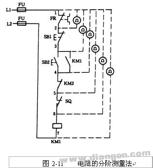
1 step measurement method. The step-by-step measurement of the resistance is shown in Figure 2-11.
When the start button SB2 is pressed, the contactor KM1 does not pull in, and the electrical circuit has an open circuit failure.
Before using the multimeter's electrical blocking test, first disconnect the power supply, then press SB2 to not relax, first measure the resistance between the two points of l-7, such as the resistance value is infinite, indicating that the circuit between l-7 is open. Then, the resistance values ​​between the points of l-2, l-3, l-4, l-5, and 1-6 are measured step by step. If the circuit is normal, the resistance value between the two points is "0"; when the resistance value between a certain number is measured to be infinite, it means that the contact or connecting wire that the meter has just crossed is open.
2 segmentation measurement method. The segmentation measurement of the resistor is shown in Figure 2-12.
Figure 2-12 Segmentation measurement of the resistor 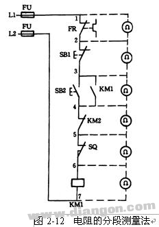
When checking, first cut off the power, press the start button SB2, and then measure the resistance between the adjacent two label points l-2, 2-3, 3-4, 4-5, 5-6 one by one. If the resistance between two points is infinite, the contact or connecting wire between the two points is broken. For example, when the resistance value between two points is measured to be infinite, the stop button SB1 or the wire connecting SB1 is broken.
Note on resistance measurement:
i) Always disconnect the power supply when checking for faults using resistance measurement.
Ii) If the circuit under test is connected in parallel with other circuits, the circuit must be disconnected from other circuits, otherwise the measured resistance value is not accurate.
Iii) When measuring high-resistance electrical components, rotate the multimeter's selector switch to suit electrical blocking.
(3) Short-circuit method: It means that the two equipotential points in the machine line are short-circuited with wires to narrow the fault range, thereby determining the fault range or fault point.
Figure 2-13 Local shorting method 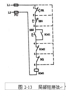
1 Local Shorting Method The local shorting method is shown in Figure 2-13.
When the start button SB2 is pressed, the contactor KM1 does not pull in, indicating that the circuit is faulty. Before the inspection, use a multimeter to measure the voltage between two points of l-7. If the voltage is normal, press the start button SB2 to not relax, then use a well-insulated wire to short the adjacent two points, such as short Connect l-2, 2-3, 3-4, 4-5, 5-6. When shorted to a certain point, the contactor KM1 is closed, indicating that the open circuit fault is between these two points.
Figure 2-14 Long and short connection 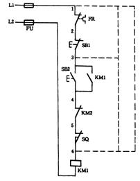
2 Long and short connection method Short circuit connection method to check the open circuit fault is shown in Figure 2-14.
Long and short is a method of shorting two or more contacts at a time to check for faults.
When the normally closed contact of the FR and the normally closed contact of the SB1 are in poor contact at the same time, if the above short-circuit method is used to short-circuit 1-2 points, pressing the start button SB2, KM1 still does not pick up, so it may cause judgment error. The long and short connection method is used to short-circuit 1-6, such as KM1 pull-in, indicating that there is an open circuit fault in the circuit of l-6, and then short-circuit l-3 and 3-6, if short-circuit l-3, KM1 sucks If it is combined, it indicates that the fault is within the range of l-3. By shorting 1-2 and 2-3 with the local shorting method, the circuit breaker fault can be quickly eliminated.
Short-circuit check points:
i) Short-circuit method is to operate with insulated wires by hand, so be sure to pay attention to safety and avoid electric shock accidents.
Ii) The shorting method is only suitable for checking for open circuit faults such as wires and contacts with very small voltage drops. For electrical faults with large voltage drop, such as resistors, coils, windings, etc., short circuit can not be used, otherwise short circuit faults will occur.
Iii) For some important parts of the machine tool, the short circuit method must be used to ensure that there is no accident in the electrical equipment or mechanical parts.
Example of machine circuit troubleshooting The following examples illustrate the application of these three common maintenance methods in the case of a lathe with energy-consuming braking failure.
1. The main circuit fault is eliminated in the main circuit. By single-tube rectification, the alternating current is converted into direct current and connected to the stator winding of the motor to generate a braking torque opposite to the direction of rotation of the motor rotor, thereby causing the motor to stop rapidly. The energy consumption brake fault is common in the main circuit. The damage or contact of the fuse FU2 and the diode VD, the contact of each contact of the KM4 and the contact points of each connection point can be detected by using a multimeter to check the fault point.
Example 1 If the 203 line on KM4 (V11-W12) in the main circuit is loose, use the resistance method to find the fault point.
Select the RX10 resistor file of the multimeter, a rod (due to the unidirectional conductivity of the diode, so select the red rod here) to move at V11, and the other rod (ie black rod) gradually descends from 201 points. Move and push the KM4 contact to close when passing the KM4 contact (just hold down the KM4's armature). If during the measurement, the resistance value between V11 and a certain point (such as 203 on KM4) is measured to be infinite, then the point (203 points on KM4) or the component (KM4 contact) is the fault point. .
2. Elimination of KT coil branch fault
The path to energize the KT coil is:
01→FU5→02→SQ1(02-12)→KM1(12-13)→KM4(13-16)→KT coil→00
The 2KT coil of Example 2 must not be powered. If the fault point is on line 16 of contact KT, the fault point is found by voltage method.
Select the multimeter's AC voltage 250V range, one stick is placed on the 02 line, and the other stick is placed on the 12, 13, 16, 00 line. When the multimeter has a voltage indication (here 127V), the fault The point is the point or the component. In this example, when another stick moves to line 16 on KT, the multimeter still has no voltage indication, and when it moves to line 0 on KT, there will be a voltage indication of 127V. At this point, the fault point can be determined. Line 16 on KT.
3. Elimination of KM4 coil branch fault
The path for energizing the KM4 coil is:
01→FU5→02→KT(02-13)→KM1(13-14)→KM2(14-15)→KM4 coil→00
Example 3KM4 coil must not be powered. If the fault point is on line 14 on contact KM1 (13-14), use short circuit to find the fault point.
Because KT can get electricity, if there is only one fault point in the line, then the fault phenomenon should be that KT pull-in is not released, and the equipotential point line 13 and line 15 can be short-circuited. If the KM4 coil can be powered at this time. , indicating that the fault range is between line 13 and line 15, in the case of power failure, the fault point can be quickly found by the resistance method.
Passive Stylus Pen,Custom Stylus Pen,Stylus Pen For Surface,Smart Stylus Pen
Shenzhen Ruidian Technology CO., Ltd , https://www.wisonens.com