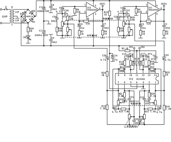
This stereo power amplifier is a stereo power amplifier mainly composed of integrated circuit TDA2030A. It uses a typical power amplifier circuit, which has low distortion, few peripheral components, high stability, wide frequency response range, high fidelity, high power, etc. Advantages: At the same time, the four op amp GL324A is used to process the input audio signal and control the high and low bass, thereby ensuring the sound quality of the output sound. This is a self-made audio kit suitable for radio enthusiasts and audio enthusiasts. This power amplifier actually listens, the treble is soft and delicate, and the bass is full and round. 1. Working principle The core chip used in this stereo power amplifier is the international high-fidelity audio power amplifier integrated circuit TDA2030A. This circuit consists of three parts, namely the power supply circuit, the power amplifier of the left and right channels and the input signal processing power supply (four op amps). The power transformer reduces 220V AC to dual 12V low-voltage AC, and after bridge rectification, it becomes ± 18V DC. As the power supply for the power amplifier and operational amplifier, D5 and R29 form a power indicating circuit to indicate whether the power is normal. Switch K is switch. Four operational amplifiers GL324A (or LM324) and peripheral components form a high and low bass control circuit and audio input signal processing circuit, C16 and C18 are the input coupling circuits of the two signals, W1 is the two-way bass control potentiometer, W2 is the two Road tweeter control potentiometer, C25, C26 are output coupling capacitors. Pin 4 and pin 11 of GL324A are the terminals of positive and negative power supplies, and pins 3 and 5 are grounds. The integrated circuit used for the two-way power amplifier is TDA2030A. One pin is the positive phase input terminal, and the second pin is the inverting input terminal. C3 and C6 are the coupling capacitors of the left and right input terminals respectively. R1, R4 and C2 form The negative feedback circuit of IC1, R6, R7, C5 constitute the negative feedback circuit of IC2 to improve the sound quality. Pin 5 and pin 3 are connected to positive and negative power sources respectively. Pin 4 is the output terminal. When the load is connected to a 4Ω speaker, the effective power can reach 20W. W3 is a two-way balanced potentiometer and W4 is a two-way volume potentiometer. Second, welding and installation Generally, install low and heat-resistant components first, and then install integrated circuits. Welding and installation should be carried out as follows: (1) Check the quantity and quality of components, and replace unqualified components in time; (2) Determine the installation method of the components by the hole distance, the horizontal installation of the resistor, and the capacitor 3. Electrolytic capacitors are installed vertically and are required to be close to the circuit board. (3) Be careful when inserting IC1 and IC2. After inserting all the feet, solder, and pay attention to the hole position of the heat sink. The heating time and the amount of tin used in each solder joint should be appropriate to prevent virtual soldering, false soldering and short circuit. After welding, cut off the excess pins, and check all solder joints to confirm that they are correct before power-on testing. At the same time, we must pay attention to the wiring of the primary and secondary power transformers and the switch and the circuit board. There must be no mistakes. IC1 and IC2 are connected to the radiator with self-tapping screws. 3. Test and Assembly 1. Power-on test After all components and plug-ins are welded, they can be energized after careful inspection. The positive and negative power supply measured with a multimeter DC voltage should be about ± 18V. The light-emitting diode D5 emits light. After connecting the sound column, touch the input terminal with your hand. IN1, IN2, there should be a strong induction signal, indicating that the circuit is normal. If there is no strong induction signal, it means that the power amplifier circuit is not working. It is necessary to further check whether the installation and welding of IC1, IC2, IC3 and peripheral components are normal. 2. Complete machine assembly Technical area detailed analysis of Doherty power amplifier design load traction principle (top) detailed analysis of Doherty power amplifier design how to improve efficiency (lower) voltage follower input and output error analysis lm386 power amplifier energization will produce noise causes and treatment methods analysis class d Solve the effect of power amplifier on emi  Follow WeChat Interesting and informative information and technical dry goods  Download Audiophile APP Create your own personal electronic circle  Follow the audiophile class Lock the latest course activities and technical live broadcast Collect People collection share it: ![]() '+ data.username +' '+ data.username +'
|


