Design scheme of analog circuit in ECG acquisition system
The electrocardiogram signal is a weak signal on the human body surface. The frequency range is 0.05 ~ 200Hz, the voltage amplitude is 0 ~ 5mV, and the impedance of the signal source is thousands of ohms to hundreds of ohms. There is a lot of noise, so the reasonable design of the ECG acquisition system is the key component to whether the correct ECG signal can be obtained. The measurement conditions of ECG signals are quite complicated. In addition to the interference of internal body interference signals including myoelectric signals, respiratory wave signals, EEG signals, etc., they are also subject to external interference of 50HZ city power, baseline drift, electrode contact, and other electromagnetic equipment Therefore, how to effectively suppress various interferences under strong noise will become the key to the design of ECG acquisition system.
1 Brief introduction of ECG acquisition system
The complete ECG acquisition system includes analog and digital parts. The analog part mainly completes the pickup, amplification and filtering of ECG signals. The digital part will analyze and process the ECG signals obtained by the analog part, so that medical staff can draw The correct diagnosis results, so the analog circuit in the ECG acquisition system plays an important role in the ECG monitoring system. The overall structure of the ECG acquisition system is shown in Figure 1.

The ECG signal picked up by the dedicated electrode carried on the human body is first preliminarily amplified by a preamplifier, and after a certain suppression of various interference signals, it is sent to a band-pass filter to filter out interference signals outside the ECG frequency range Then, the main amplifier will further amplify the filtered signal to a suitable range, and then filter out the power frequency interference through the 50Hz notch filter, and the obtained analog ECG signal will be sent to the AD conversion system for analog-to-digital conversion and converted into a digital signal. The central processing unit is then responsible for subsequent analysis and processing.
2 preamplifier circuit
The ECG signal picked up from the surface of the human body is generally only a few millivolts. In order to improve its resolution for display and processing at the back end, the signal needs to be amplified first. In the process of ECG signal acquisition, the pre-amplifier circuit has the greatest impact on the ECG signal. To improve the performance of the ECG signal, the amplification factor of the pre-amplifier circuit cannot be selected too large (generally less than 20), otherwise it will The large interference signal (referred to the polarization voltage of the electrode) causes the amplifier to block.
For ECG signals, the collected signals belong to differential mode signals, so their amplifiers use differential amplifier circuit structures, the most commonly used are low noise, high input impedance, high common mode rejection ratio, high gain and anti-interference The powerful in-phase parallel differential amplifier circuit, commonly known as the three operational amplifier instrumentation amplifier, this system uses a general-purpose integrated operational amplifier LM324 to form this amplifier. LM324 is a 4-integrated operational amplifier. Due to its low cost and ease of use, it is widely used in control and signal amplification processes. We have carefully designed and repeated experiments in the laboratory, and the circuit composed of LM324 has successfully realized the amplification processing of the ECG signal, and its main technical indicators can meet the requirements. The LM324 can be used with a single power supply or dual power supplies. The power supply voltage can be used from + 5V to ± 15 V, and the drive power consumption is low. The differential mode gain of each group of operational amplifiers can reach 100dB. Through the rational design of the peripheral circuit, the amplifier circuit with LM324 as the main device can fully meet the requirements of high magnification and high stability ECG signal amplification processing.
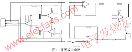
It is worth mentioning that the low current noise of the LM324 is particularly suitable for ECG applications. It has good DC characteristics: the input offset voltage is less than 5mV, the input offset voltage temperature drift is less than 7uV / ° C, and the input bias current is less than 40nA. Mode rejection ratio is up to 100dB, and its low power consumption, low power supply (down to 3V), compact package and other characteristics are excellent choices for battery-powered portable ECG monitoring systems. The principle of the amplifier circuit is shown in Figure 2.

The amplifier designed in Figure 2 is composed of two stages. U1C and U1D constitute the first stage of differential input and output stage. U2A is a basic differential proportional circuit. The total voltage gain Au is equal to the product of the two stages of gain. Because the first stage uses the same phase input and has a higher input resistance, U1C and U1D use the same characteristics of the operational amplifier, so that their common mode output voltage and drift voltage are also equal, and then through the second stage differential circuit composed of U2A , Can cancel each other, the second-stage differential amplifier circuit will change the double-ended input to single-ended output to meet the needs of grounded loads. After cascading the two-stage circuits, they complement each other to make up the shortcomings, so that the combined circuit has a series of advantages such as high input impedance, easy voltage gain adjustment, high common-mode rejection ratio, and drift cancellation. In order to improve the common mode rejection ratio and reduce the effect of temperature drift, and further improve the performance of the circuit, the measurement amplifier adopts a symmetrical structure, that is, a few external resistors R10, R11, R12, R13, R14, R15, R16 and RW2 are adjusted to make R11 = R12, R13 = R14, R16 = R15 + RW2 after adjustment. Therefore, the gain of the measurement amplifier can be easily changed by adjusting the size of the external resistor RW2.
An effective method to remove the AC common mode interference carried by the human body is to use the right leg drive circuit. In the system of Figure 2, the RL end of the right leg is not directly grounded, but connected to the output end of the amplifier. The common mode voltage is detected from the output end of the drive shield, which is amplified by the auxiliary inverting amplifier U0, and then fed back to the right leg through the resistor R1, thus obtaining the name of the right leg drive, that is, the displacement current of the human body no longer flows in Ground, but to the output of R1 and auxiliary amplifier U0. However, due to the feedback loop of the AC interference voltage in the right leg drive circuit, AC current may flow through the human body and become an unsafe factor. The current-limiting resistance cannot be very small, usually 1M or more, that is, R1 plays a role in safety protection here When a high voltage appears between the patient and ground, the auxiliary amplifier U0 is saturated, and the right leg drive circuit does not work. U0 is equivalent to ground, so the resistor R1 now acts as a current limiting protection. The interference signal is sent to the right-leg drive amplifier for inverse amplification, and transmitted to the right-leg drive electrode RL. It is a kind of deep negative feedback for the interference signal, which effectively weakens the common-mode interference signal induced on the human body.
3 Main amplifier and filter circuit
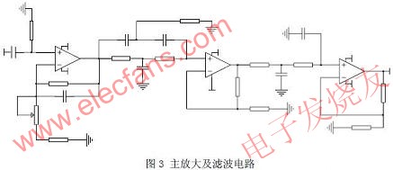
The main amplification and filter circuit of ECG is shown in Figure 3. The main interference signals in the detection signal are the polarization voltage between the electrode plate and the person, the 50Hz power frequency interference, the internal noise of the instrument and the electromagnetic field interference around the instrument, etc. To obtain a clear and stable ECG signal, the design of the filter is also very important, especially the 50Hz band stop filter is particularly important. Among the collected ECG signals, the interference signals above 200 Hz are strong, while the interference signals below 0.05 Hz are relatively weak, so in the filter circuit, the low-pass filter is used to take out the signals below 200 Hz, and then the high-pass is connected. Thereby filtering the polarization voltage and high frequency interference. U2B, resistors and capacitors form a band-pass filter in the circuit, and at the same time make the circuit have a higher input impedance. The filter circuit uses a resistance-capacitance coupling circuit, with high input impedance and low output impedance, and good isolation between input and output. Its role is to isolate the DC voltage and DC polarization voltage of the preamplifier and couple the ECG signal. In order to ensure that the ECG signal is coupled to the next stage without distortion, the RC must be coupled. The larger the RC product, the better the low-frequency response of the amplifier. However, the value of RC cannot be increased without limit, because the value of R is limited by the input impedance. If the value of C is too large, it is not only bulky, but the increase in leakage current will also cause drift. Will prolong the circuit charge and discharge time. The frequency of the human body's ECG signal is low, and the RC filter circuit can effectively avoid the defects of the active filter circuit due to the narrow bandwidth of the universal integrated op amp and not suitable for high frequency range.

4 Level up circuit
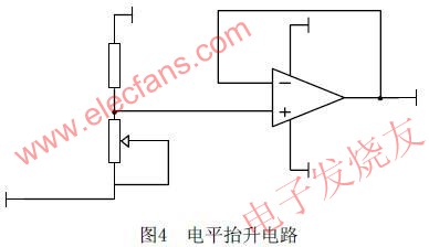
The amplified and filtered ECG signal will be sent to the A / D conversion circuit for analog-to-digital conversion, and the AD converter selected by this system is a single 5V powered MAX187, so after filtering, a level-up circuit needs to be added to convert the heart The electrical signal rises to the range of 0 ~ + 5V. The circuit design is very simple, as shown in Figure 4.

5 Results analysis
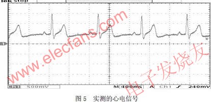
The analog circuit part of the ECG acquisition system was successfully designed and implemented through the above method. The level-up circuit is simple and reliable. The amplifier circuit has high gain, high input impedance, high common-mode rejection ratio, low noise, low drift, With characteristics such as bandwidth and dynamic range, the circuit can detect and amplify and lift the weak ECG signal through the surface sensor without distortion under a strong noise background, and obtain a better ECG signal as shown in Figure 5 As shown.

Tests have proved that the ECG signal acquisition circuit designed in this paper can obtain clinically valuable ECG data, which provides a reliable guarantee for the subsequent processing of ECG signals.
Wireless Bluetooth headphone , stereo bluetooth Headphone
Main features
1.Vibration reminding when phone call comes in.
2.rubbish finish with Detachable cable
3.Delivers enhanced audio and bass response and a host of calling features in a sleek, comfortable design.4.Unique, provides all day comfort and ease of use.
5.High quality Bluetooth Headset with music & phone functions.
6. Gift box packing per pc

Wireless Bluetooth Headphones,Wireless Headphones,Wireless Earphones,Wireless Bluetooth Earbuds
Shenzhen Greater Industry Co., Ltd. , https://www.szgreater.net