Intelligent lighting solutions based on Infineon MCU
Intelligent lighting solution based on the Infineon XMC1200 MCU. MCU can help realize intelligent LED lighting. LED lighting system manufacturers can rely on the built-in BCCU function MCU to significantly shorten the time-to-market for developing intelligent high-power LED bulbs, and help end users achieve easy and precise dimming while avoiding flickering problems. As a single-chip solution with the above features, the Infineon XMC1200 can save a lot of CPU overhead, greatly reduce software development time, and effectively reduce the risk of human error caused by human error. At the same time, the XMC1200 series MCU has the characteristics of high performance, large capacity and high reliability, which can be applied to all aspects of life and industry.
To achieve the bulb control modulation, the LED switch speed is the key. Modulation refers to the ability to quickly switch LEDs. If the switching speed is fast enough, the human eye will not be able to recognize it. The brightness seen will depend on the average time the LED is turned on. The most common modulation methods are Pulse Width Modulation (PWM) and Pulse Density Modulation (PDM) (Figure 2). Among them, PDM can achieve higher resolution at the equivalent system frequency, better electromagnetic interference (EMI) characteristics, and because of its high switching rate, it is not easy to flicker.
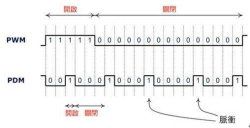
Figure 1 - PWM and PDM modulation at approximately 25% brightness
The control unit of the outdoor LED bulb includes a power supply and a driver. Among them, important components of the standard power supply include bridge rectifiers, power factor corrector (PFC) and buck converters for half-bridge resonant (LLC) resonant converters (Figure 1).
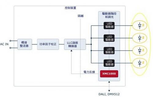
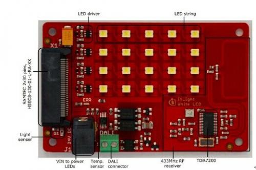
Figure 2 - Example of a four-channel LED lighting engine
The LED current is fixed through a linear or switched LED driver to a carefully selected value, and the selected LED current is dependent on the system device and the maximum brightness required, such as 350 milliamps (mA) or 700 milliamps. General street light LEDs are driven at the same current, and multi-color bulbs often used in architectural lighting may use completely different LED channel currents. When dimming, it is usually triggered by communication, such as digital addressable lighting interface (DALI) or sensor input (such as ambient light source); the brightness and / or color of the bulb is through the input of the modulation driver (Enable Input) Control it.
The microcontroller (MCU) developed by the industry for LED illumination includes a Brightness and Color Control Unit (BCCU) that generates PDM signals on up to nine channels. The special challenge of high-power dimming bulbs is that the LED driver requires the shortest dwell time, and the modulation signal of the LED driver Enable Input must remain constant for the shortest time interval. It is known from the rule of thumb that the higher the power, the longer the minimum dwell time required, in order to maintain a stable and accurate LED current. However, at high resolutions and high bit rates, especially in low brightness situations, the modulated signal may violate this requirement.
At present, the development of MCUs suitable for LED lighting in the industry can automatically rearrange the pulses in the modulated signal to automatically solve this problem. The pulses are regrouped within the packet circuit (Figure 3), generating new pulses, having the shortest width required and taking into account the resolution while remaining unshiny.
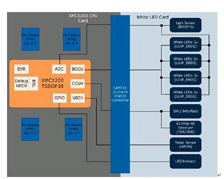
Figure 3 - Comparison of ungrouped PDM and grouped PDM paradigms
Another requirement is to minimize the load variation of the power supply (to make the load smooth), especially the LLC resonant converter is extremely sensitive to high load variations. The packet circuit in the BCCU can add a phase shift between different relative channel modulation signals to ensure that the signal changes state at different points in time.
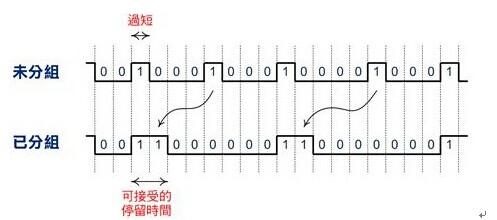
Figure 4 - System Architecture
Program features
Isolated DALI dimming interface
temperature check
Ambient brightness detection
433MHz RF control mode
Semi-transparent Liquid Crystal Display
Semi-Transparent Liquid Crystal Display,2.7Inch Translucent Liquid Crystal Display,Thin Translucent Liquid Crystal Lcd Display,Fast Response Lcd Display
Dongguan Yijia Optoelectronics Co., Ltd. , https://www.everbestlcdlcms.com