DIY makes a simple and beautiful solar LED fox pendant
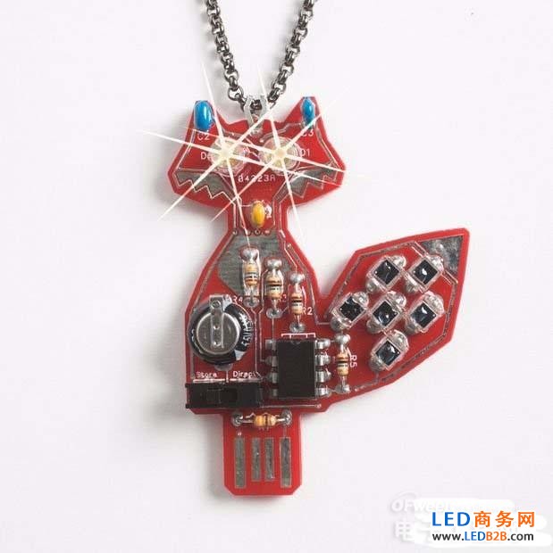
Figure 1 LED fox pendant
Step 1: Prepare the welding tool (as shown in Figure 2)
1. Soldering iron 2. Solder 3. Diagonal cutters You can also choose support frames and needle-nosed pliers to help with the operation.
Step 2: Schematic and parts (as shown in Figure 3/4)
1. C2-47uF ceramic capacitor (blue-large)
2. C3-10uF ceramic chip capacitor (blue - small)
3. C4-0.1uF time-scale capacitor (brown)
4. U2-MCP6542 master IC
5. SC1 to SC6 - BPW34 ($0.4135) Photodiode 6. R5-330 ohm resistor (orange belt)
7. R1/R2/R3/R4-10M resistors (brown and black)
8. D1 and D2-amber LEDs
9. Switch - Single pole double throw switch 10. C1-0.033uF (black)
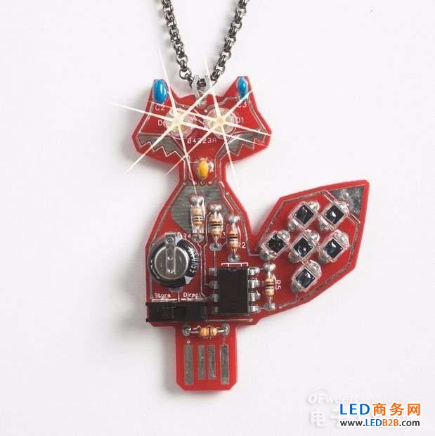
Figure 3 parts 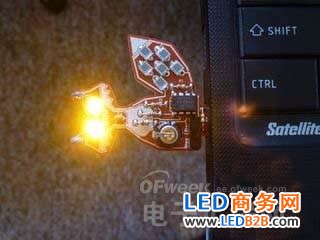
Figure 4 schematic
Step three: soldering capacitor
Assemble our work from the beginning of the capacitor. Although these capacitors look similar in appearance, it is important to solder the corresponding capacitors to the appropriate locations! Second, these capacitors are not divided into positive and negative, so you only need to divide the position of these capacitors. Let's tell you how to read the number on the resistor.
The number above a.C2 is read as "476", the first two digits are its effective digits, the third digit is the multiplier, and the unit of resistance is Farah, so 476 stands for 47*10^6 Farah b.C3 The above number is read out as "106", which means that the size of C3 is: 10*10^6 Farah c. The number above the c.C4 is "104", which means the size of C4 is: 10*10^4 Farah
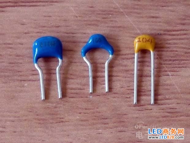
Figure 5 capacitor
If you have any experience with soldering before, here are some basic steps to introduce you. If you already have welding experience, you can skip this part.
1. Hold the hand grip of the soldering iron with your right hand and control the hot tip of the soldering iron near the contact point of the capacitor pin. The hot tip of the soldering iron needs to reach the pin of the capacitor and the solder joint of the board. 2. Hold for 2-3 seconds. 3. Touch the end of the solder to the place where you are soldering now. If the soldering iron is hot enough, you will Immediately see the solder melts.
4. The solder melts onto the solder joint and the capacitor pin. It will connect the two like water. 5. Once the solder covers the solder joint with the capacitor, remove the solder and remove the soldering iron. 6. During the cooling of the solder, do not touch it until the solder solidifies. (Because it is still hot, the temperature is up to 380 degrees) Generally, the cooling of the solder takes 2-3 seconds. 7. Repeat steps 1-6 to solder other capacitors.
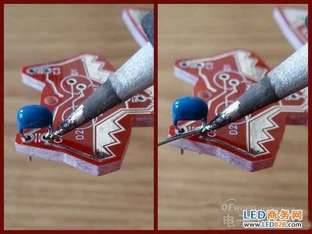
Figure 6 welding capacitor
The material of this product is PC+ABS. All condition of our product is 100% brand new. OEM and ODM are avaliable of our products for your need. We also can produce the goods according to your specific requirement.
Our products built with input/output overvoltage protection, input/output overcurrent protection, over temperature protection, over power protection and short circuit protection. You can send more details of this product, so that we can offer best service to you!
Lcd Adapter,Mini Size Lcd Adapter,Security Lcd Adapter,Waterproof Lcd Adapter
Shenzhen Waweis Technology Co., Ltd. , https://www.waweispowerasdapter.com