Conditions for signal transmission without distortion _ conditions for distortion-free transmission
Distortion-free transmission refers to the output signal or input signal of a system that has no change in amplitude and the time of occurrence.
To maintain the system's distortion-free transmission signal, from the frequency domain analysis, you can take the Fourier transform on both sides of Equation 1 and use its time-shift property.

due to

So the system function without distortion transmission is (Equation 2)

which is

Therefore, the distortion-free transmission system should satisfy two conditions in the frequency domain:
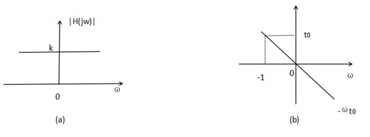
(1) The amplitude-frequency characteristic of the system should be constant k over the entire frequency domain, that is, the passband of the system is infinite;
(2) The phase frequency characteristics of the system should be proportional to w over the entire frequency range, ie  ,as shown in picture 2.
If we take the inverse Fourier transform of Equation 2, we can see that the unit impulse response of the system is

This formula shows that the unit impulse response of a distortion-free transmission system is still an impulse function, but it is not necessarily in unit 1 in intensity, and it is not necessarily located at t=0 in position. Therefore, Equation 3 gives the conditions of the distortionless transmission system from the time domain.
The amplitude-frequency characteristics of distortion-free transmission systems should be kept constant over an infinitely wide frequency range, which is not possible. In fact, since all the signals are always reduced with increasing frequency, the system can obtain satisfactory transmission quality as long as it has a large enough bandwidth to ensure that the frequency components containing most of the energy can pass. .
Causes of signal distortion caused by linear systemsThe amplitude of each frequency component produces different attenuation - amplitude distortion
The phase shift produced by each frequency component is not proportional to the frequency, and the relative position of each frequency component of the response changes on the time axis - phase distortion
Condition for signal transmission without distortionTime domain condition: y(t)=kf(t-t0) or h(t)=kδ(t-t0).
The frequency domain condition Y(jw)=kX(jw)e^(-jwt0) or H(jw)=ke^(-jwt0).
The time domain is a description of the relationship of a mathematical function or physical signal to time. For example, a time domain waveform of a signal can express a change in signal over time. If discrete time, function or signal in the time domain is considered, the values ​​at each discrete time point are known. If continuous time is considered, the value of the function or signal at any time is known. When studying the signal in the time domain, the oscilloscope is often used to convert the signal to its time domain waveform.
Undistorted transmission of digital signalsIn order to study the distortion problem of waveform transmission, we first look at the typical model of the baseband signal transmission system, as shown in the following figure. At the transmitting end, the digital baseband signal is input to the channel via a transmission filter, and the function of the transmission filter is to limit the transmission band and prevent unnecessary frequency components from interfering with adjacent channels. The baseband signal is often mixed with noise when transmitted in the channel, and due to the limited bandwidth of the channel, it is inevitable that the distortion of the transmission waveform is caused.
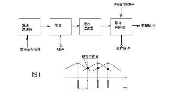
Therefore, there is definitely a big difference between the waveform input at the receiving end and the original baseband signal. If the sampling decision is made directly, a large misjudgment will occur. Therefore, a sampling filter is passed before the sampling decision, which filters out-of-band noise on the one hand and equalizes the distortion waveform on the other hand. The sampling and decision circuit regenerates the digital signal and improves the quality of the output signal.
According to the basic principle of spectrum analysis, the distortion of the baseband signal in the frequency domain must be extended in the time domain, which brings about crosstalk between the symbols. Therefore, the main cause of the decision error is the inter-code crosstalk caused by the poor transmission characteristics (including the transmit and receive filters and channel characteristics) in addition to the noise. When the baseband pulse sequence passes through the system, the filtering of the system causes the pulses to be stretched (the period in the time domain becomes longer), and in time, they overlap into adjacent time slots (as shown in Figure 1). The receiving end samples each point in the agreed time slot, and compares the signal amplitude measured at the sampling time with the threshold level to determine the original pulse message. If the smearing of adjacent pulses exceeds the threshold level, the transmitted "0" is judged as "1". In practice, there may be several trailing superpositions of adjacent pulses. This phenomenon of overlapping pulses and causing difficulty in decision at the receiving end is called intersymbol interference.
It can thus be seen that the main factor that constrains the transmission of the baseband signal is the frequency characteristics of the system. Of course, the transmission band can be intentionally widened to reduce this interference to any degree. However, this can result in unnecessary waste of bandwidth. If you spread too much, you will introduce too much noise into the system. Therefore, an alternative approach should be explored, either by designing the signal waveform or by using a suitable transmission filter to greatly reduce or eliminate such interference with minimal transmission bandwidth.
Nyquist et al. studied the above situation and proposed a distortion-free condition for digital signal transmission, called the Nyquist first criterion. The content is that when the digital signal sequence is transmitted through a certain channel, such as the signal transmission rate Bb=2Bc (Bc is the channel physical bandwidth), the interval of each symbol is T=1/2Bc, and the digital sequence can be codeless. Interference has been transmitted. At this time, Bc=1/2T is called the Nyquist bandwidth, and T is called the Nyquist interval.
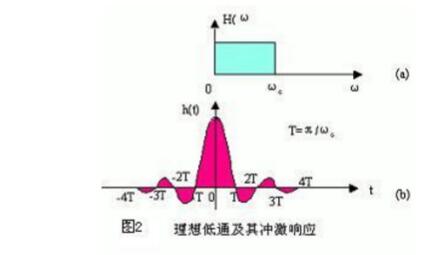
As mentioned above, the bandwidth of any transmission channel is limited, and its characteristics are equivalent to a low-pass filter. The ideal low-pass filter has an impulse response of sinωct/ωct, the waveform of which is shown in Figure 2b. If the binary digital sequence is transmitted, its band utilization is Bb/Bc=2bit/s/Hz (where Rb is the transmission code rate, the unit is bps, and BC is the Nyquist bandwidth). Band utilization if the sequence is an n-ary signal
It is 2log2nbit/s/Hz (such as 16QAM24=16, so it is hexadecimal, 64QAM26=64 is hexadecimal).
The Nyquist first criterion is essentially a sample-free distortion-free condition, which points us to the fundamental relationship between inter-symbol interference and the full use of frequency bands. At the same time, after the signal is transmitted, although the whole waveform will change, as long as the sample value remains unchanged, the method of re-sampling (ie, the regenerative decision) can still restore the original signal without any error. For this reason, the ideal low-pass response is adopted. Waveform reception does not cause intersymbol interference.
However, in practice, the ideal low-pass characteristics are difficult to achieve. This is first because the ideal low-pass characteristic is not physically achievable, and secondly, the attenuation oscillation of the tail of the impulse response pulse waveform is relatively large. If the accuracy of the timing is slightly worse, the sampling moment will appear when the deviation occurs. Considerable inter-symbol interference.
In practical applications, we use a channel with roll-off characteristics. This channel can overcome two shortcomings of the ideal low pass characteristics.
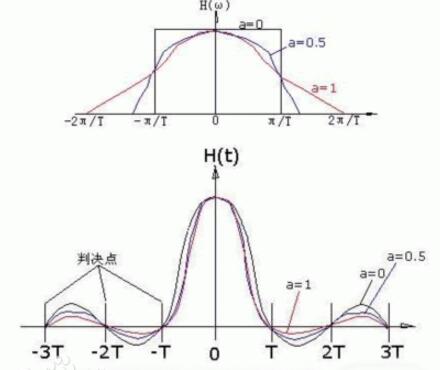
The roll-off characteristic channel has a wider bandwidth than the Nyquist bandwidth, and the degree of increase is represented by a roll-off coefficient α. a = fc2 / fc1, the range of a value is 0 ≤ a ≥ 1, where fc1 is the cutoff frequency of the ideal low pass, and the cutoff frequency of the fc2 roll-off characteristic channel. The characteristics and impulse response of the channel with roll-off coefficient a are shown in Fig. 3.
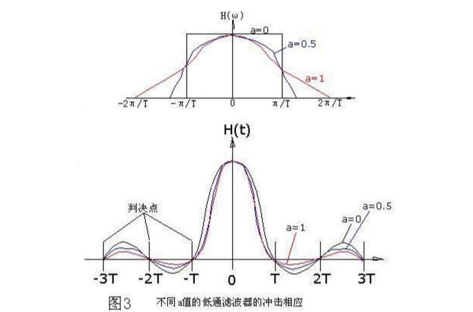
As can be seen from the above figure:
1. When a=0, the system is ideal low-pass characteristic, and a≤1 is the raised cosine roll-off filtering characteristic.
2. For the raised cosine roll-off characteristic of a "0", the value of the impulse response H(t) is divided by the sampling point.
When t=0 is not zero, the values ​​of the other sampling points are all zero, and after t·T, a zero point is added between each sample point, so that the “tail†decays faster with time. This is advantageous for eliminating intersymbol interference and reducing timing jitter.
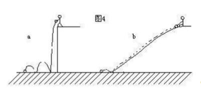
3. The crosstalk value of the raised cosine roll-off signal at each sampling point (-3T, -2T, ..... 2T, 3T in the figure) is always zero, so it satisfies the sample value without distortion transmission condition. The smaller a is, the larger the fluctuation of the waveform tailing is, but the bandwidth required for transmission is reduced, that is, the frequency band utilization is high; on the contrary, the larger a, the smaller the tailing oscillation fluctuation, and the bandwidth required for transmission increases, that is, the frequency band. The utilization rate becomes lower, and the limit case is a=1. At this time, the roll-off characteristic occupies twice the bandwidth ratio a=0, and the band utilization rate is only half of the limit case. This situation can be imaged using Figure 4. The ball in Figure 4a falls from the cliff, and the rebound to the ground is high and the bounce time is long (long tail). The ball in Figure 4b rolls down from the ramp, and the rebound is small and the bounce time is short after landing.
4. Considering that the received waveform is further sampled in the regenerative decision to achieve distortion-free transmission, in the actual sampling, the sampling moment cannot be completely free of errors, and the sampling pulse width cannot be zero. Therefore, in order to reduce the sampling timing The influence of the pulse, the value of a cannot be too large, usually a0.16 is selected. For example, in the DVB-C system, the I and Q signals are obtained before modulation, and the raised cosine characteristic of a=0.16 is used for filtering. A calculation example based on modulation transmission method, for example: a=0.16, using 64QAM modulation, the band utilization ratio N=log264=6 (the number of bits per modulation symbol), the DVB-C system with the channel physical bandwidth of W=8MHz To find its effective transmission rate SS, calculate as follows:
1. First calculate its symbol rate D=W/(1+a)=8/(1+0.16)=6.8966Ms/s
2, the total transmission rate C = D * N = 6.8966 * 6 = 41.379Mbps
3. The channel coding of DVB-C is RS (204, 188), so the effective transmission rate
CO=C*188/204=38.134Mbps
In general, since there is jitter in the transmission channel, the timing at the time of decision cannot be made very accurate, so that the tailing of the impulse response waveform of the channel with low-pass filtering characteristics will cause intersymbol interference. To this end, this smearing effect can be attenuated by increasing the value of a, thereby reducing inter-symbol interference, but at the expense of the bandwidth utilization of the channel.
In order to further overcome the influence of inter-symbol interference, the channel characteristics are usually compensated by adding an adjustable compensation filter in front of the sampling speculator at the receiving end, so that the performance of the actual system is as close as possible to the optimal performance. It is called equilibrium.
The performance of the baseband system can be compensated in the frequency domain or in the time domain. The former is frequency domain equalization and the latter is time domain equalization. The basic principle of frequency domain equalization uses the frequency characteristics of the tunable filter to compensate the frequency characteristics of the baseband system, so that the overall characteristics of the baseband system including the tunable filter are as close as possible to the optimal system characteristics. The following discussion focuses on time domain equalization.
The so-called time domain equalization is to directly use the waveform compensation method to correct the waveform distortion caused by the baseband characteristic step ideal, so that the inter-code interference of the corrected waveform at the sampling decision time is as small as possible, so the time domain equalization is also called waveform equalization. The principle can be illustrated in Figure 5:

The solid line in the figure is a single impulse response signal at the input of the sampled decider. Due to the channel characteristic step, the distortion tailing is generated, which causes crosstalk at each sampling point of t-3..........t3. If the equalizer can produce the compensation waveform shown by the dashed line in the figure, the waveform corrected by it is as shown in Fig. 5b, and the values ​​on all the sampling points except for t0 are zero, thereby eliminating inter-symbol interference.
The compensation waveform required for time domain equalization can be obtained by delaying the weight of the received waveform (plus a certain gain), so the equalization filter is actually composed of a tapped delay line plus some variable gain amplifiers, as shown in the figure. 6 shows:

It has a total of N delay lines. The delay time of each delay line is equal to the width T of the symbol. A total of N+1 taps are drawn between the delay lines of each section. The output of each tap is variable gain. Negatively adjustable) The amplifier d is weighted and then added. Therefore, when the input has a distorted waveform, the crosstalk of the output signal to the other symbol waveform can be minimized by appropriately selecting the gain of the variable gain amplifier.
The equalization filter is also called the transversal filter. In theory, the equalization filter must have an infinite number of taps to make accurate compensation. This is of course possible, because the more taps, the higher the cost and the more difficult the adjustment, in order to make Inter-code interference is minimal, and the relationship between the finite-length lateral filter tap gain d and the output signal needs to be found.
In addition, as mentioned above, the noise of the channel is also affected by the misjudgment. So what is the relationship between the noise, bandwidth, and transmission rate of the modulation transmission channel? Let me take a look at the famous Shannon formula: C=Wlog2(1+S/N). We can see from the Shannon formula: (C is the channel capacity, W is the channel bandwidth, no is the noise power density, N noise power, S Signal power.)
1. S/N (SNR) ↑, C↑.
2. If N→0, SNR→∞, C→∞. The channel capacity of the interference free channel is infinite.
3, W↑, C↑, but tend to a limit. Because W↑, N=W*n0↑.

4. If C is a constant, W and SNR can be interchanged. (spread spectrum communication)
5. The channel capacity is C, and the information rate of the source is R. If R "C, the channel coding method can be used to achieve error-free transmission.
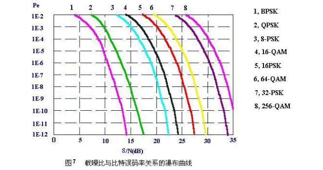
As can be seen from Figure 7, for any given modulation technique, the higher the signal-to-noise ratio (S/N) of the transmission channel, the better its bit error rate (BER) characteristics. In other words, for any given modulation technique, if the bit error rate characteristic of the transmission channel is desired to be better, the signal to noise ratio of the transmission channel is increased.
Of course, the above analysis is a conclusion in an ideal situation, and the actual situation is much more complicated. However, whether it is noise, intermodulation, echo or intrusion noise, the result is that the signal-to-noise ratio of the channel is degraded, and finally the error-free bit error rate BER of the channel is degraded.
It can be seen from Fig. 7 that the position of the curve on the horizontal axis depends on the modulation mode, and the better the noise immunity of the modulation mode, the smaller the S/N value required by the transmission system to obtain the same BER value. Generally speaking,

In summary, since the digital signal is a pulsed rectangular wave, its spectrum is infinitely wide, but the bandwidth of the transmission channel is limited, and its characteristics are equivalent to a low-pass filter. The digital pulse signal passes through a low-pass filter and will lose a considerable part of the high-frequency spectrum, causing the signal to be distorted. For this reason, the digital reproduction signal is regenerated by the decision-regeneration method at the receiving end.
Since the digital pulse signal is distorted when passing through the channel, the period in the time domain is lengthened to cause inter-symbol interference. These intersymbol interferences will cause the decision to be misjudged, causing the reconstructed data pulses to be erroneous. In order to reduce inter-symbol interference, the channel may have a raised cosine roll-off characteristic such that the inter-code interference is controlled below the decision threshold level. At the receiving end, we can also eliminate the inter-symbol interference at the decision point by equalization technology, so that the transmission channel reaches the optimal state, thereby realizing the distortion-free transmission of the digital signal.
In the channel transmitted by modulation mode, under certain channel bandwidth and required data rate and required bit error rate, we can achieve the data transmission requirements through channel adjustment and selection of corresponding modulation methods.
  Copper Lugs,Copper Cable Lugs,Plating Copper Cable Lugs,Copper Tube Terminal Lugs
Taixing Longyi Terminals Co.,Ltd. , https://www.lycopperlugs.com