Audio system design based on intelligent interface
With the development of modern electronic technology, the development of interface technology has become more and more rapid, and the USB interface has developed and expanded in this context. In traditional hardware architectures, interfaces are considered to be part of the corresponding external device, and each interface can only be connected to the same device. Although several devices of the same type can be connected to the same interface through the so-called “daisyohain†method, different types of devices cannot be connected to the same interface. Since the devices of the USB interface are more and more abundant, the types are more and more The more you come in, to meet this demand, here is a USB 2.0 interface solution that reads various USB devices through the USB interface; reads various mainstream memory cards through the SD card interface. The solution supports commonly used USB storage devices (including USB flash drive / USB hard drive / USB flash drive / USB card reader) and SD card (including standard capacity SD card and high capacity HC-SD card and protocol compatible MMC card and TF card) ). This paper proposes a smart multi-interface full hardware audio system solution, which further enhances the scalability of the audio system. In principle, it can connect most of the current mainstream storage devices and realize the expansion of one device for multiple purposes. It can further improve the utilization rate of existing resources, has certain economic and social benefits, and adopts power control methods such as full hardware decoding and single-chip frequency reduction work, so that the power consumption of the whole system is reduced to about 50% of traditional similar devices. , in line with the theme of China's energy conservation and environmental protection.
l hardware system design
1.1 Chip Overview
ATmega128 is a low power 8-bit CMOS microcontroller based on an enhanced AVR RISC architecture. Due to its advanced instruction set and single clock cycle instruction execution time, the ATmega128 has a data throughput rate of up to 1 MIPS/MHz. The AVR core has a rich instruction set and 32 general purpose working registers. All registers are directly connected to the arithmetic logic unit (ALU), allowing one instruction to simultaneously access two independent registers in one clock cycle. This architecture greatly increases code efficiency and has up to 10 times the data throughput rate compared to conventional CISC microcontrollers.
CH376S is a file management control chip for reading and writing files in a USB flash drive or SD card. CH376S supports USB device mode and USB host mode, and has built-in basic firmware of USB communication protocol, firmware for handling special communication protocol of Mass-Storage mass storage device; communication interface firmware of SD card and management of FAT16, FAT32 and FAT12 file system The firmware supports commonly used USB storage devices and SD cards.
The VS1053B is a single-chip Ogg Vorbis/MP3/AAC/WMA/MIDI audio decoder and IMA ADPCM/user-loadable Ogg Vorbis audio encoder. It supports CD-level audio playback and recording. The chip contains a high performance and low internal. The DSP processor core VS_DSP consumes 16 KB of instruction RAM and 0.5 KB of data RAM. The VS1053B has a serial control and data input/output interface, eight GPIO interfaces, a high performance variable sample rate DAC and ADC, a stereo audio input interface and a stereo audio output interface. PL2303 is used to convert USB to standard RS 232 serial port, 2 independent large buffers for 2 bus connections, large data buffer for USB bulk data transfer, and automatic handshake mode for serial communication Therefore, it can reach a baud rate much larger than the standard UART controller. The PL2303 supports USB power management and remote wake-up protocols. In this design, the PL2303 chip is mainly used to combine the download line and the power supply module of the main control unit into one, which greatly simplifies the design complexity of the system. The NOKIA 5110 liquid crystal display is a traditional dot matrix liquid crystal display, and does not have built-in English and Chinese character font, so in the process of NOKIA 5110 liquid crystal display, the MCU needs to convert the ASCII code value read from the memory into the corresponding English and Chinese dot matrix information, and then transmit the dot matrix information to the liquid crystal display through the serial port. display.
1.2 hardware design block diagram
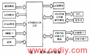
The hardware system is mainly composed of a main control module, a smart expansion interface, an audio codec module, a liquid crystal display module, a keyboard LED indication module, and a JTAG/ISP/RS 232 download interface, and the logical connection diagram is as shown in FIG. 
1.3 interface design
1.3.1 VS1053B and keyboard and LCD interface design
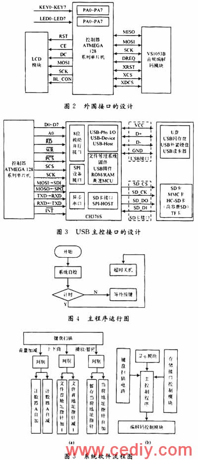
The corresponding functions of the keyboard control unit of KEY1 to KEY7 are shown in Table 1. LED1~LED7 correspond to the button indicator, such as button KEY1 is pressed. Then the LED1 light is on. The peripheral interface is shown in Figure 2. 
1.3.2 USB host device interface design
The interface design of the USB host device is shown in Figure 3. 
This article refers to the address: http://
The system software design mainly includes the main program, the interrupt control subroutine, the keyboard scanning subroutine, the LCD control subroutine, and the peripheral module control program. The main program running process is shown in Figure 4, and the software system flow chart is shown in Figure 5.
2 software system design
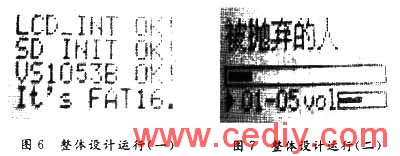
The entire design operation is shown in Figure 6 and Figure 7. 
3 Conclusion
Through this design, the control function of the single-chip microcomputer in the intelligent multi-interface design is further enhanced, and the processing method in the case of multiple interruptions. In the MCU application system, the function of man-machine dialogue is usually required, and the data can be input at any time, and various corresponding control commands are issued, and finally the operation result is output to the LCD display through the output interface. Since the LCD display of the design belongs to the traditional liquid crystal display and does not have any fonts built in, it is necessary to read the Chinese character dot matrix information in the SD card Fat file system through the single chip microcomputer, convert the ASCII into the corresponding dot matrix information, and then display it. Further increasing the difficulty of system control.
Since the system can reuse the existing resources, the solution using the intelligent interface can flexibly read and write various storage devices, thereby further improving the utilization of resources, so the system has certain social value and Prospects.
Ferrite Core Transformer,Ef 25 Transformer,Ee16 Ferrite Core Transformer,Efd Ferrite Core Transformer
IHUA INDUSTRIES CO.,LTD. , https://www.ihua-magnetics.com