12v boost circuit diagram summary Daquan (detailed of ten 12v boost circuit schematics)
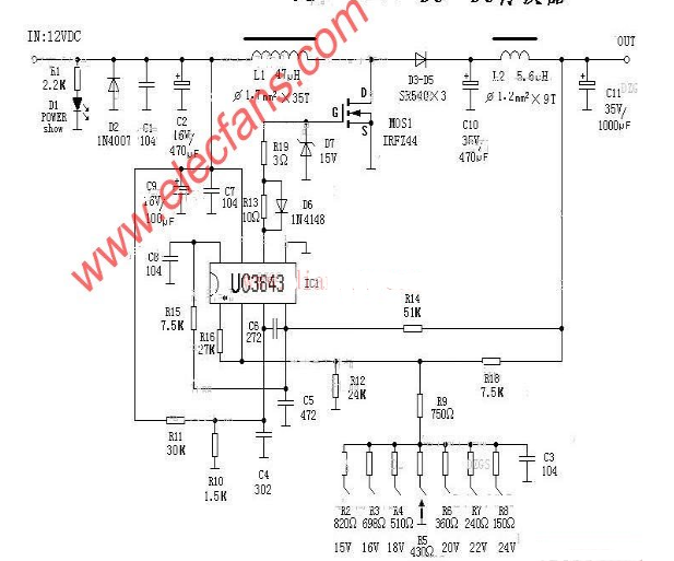
Change the resistance, you can change to 15V, 16V, 18V, 20V, 22V, 24V and other different types of voltage values.
L1 uses a magnetic ring with a diameter of 2cm, and the polyester enameled wire of 1.7 is tightly wound around 35åŒ, and then sealed with silicone rubber, otherwise it is easy to produce a sizzling sound.
At the same time, we must pay attention to the direction of the line, otherwise it will produce sizzling sound and self-excitation caused by the wire to cause FET heating and damage. Conditional UG3843 patch components can be used.
L2 can be tightly wound with the magnetic ring on the waste energy-saving lamp, no special requirements.
MOS1 can be used with 75NF75, 60N06, IRF2807 (power tube inside the battery car controller).
This circuit can be arbitrarily selected between 15-24V, such as reasonable routing, reasonable component selection, and normal operation without debugging.
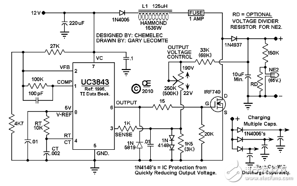
This circuit uses a boost circuit made by UC3843. The voltage input is 12V and the boost voltage can be adjusted from 22V to 190V. This circuit is suitable for the ignition of rockets or fireworks. Making this circuit is at your own risk.
Circuit schematic
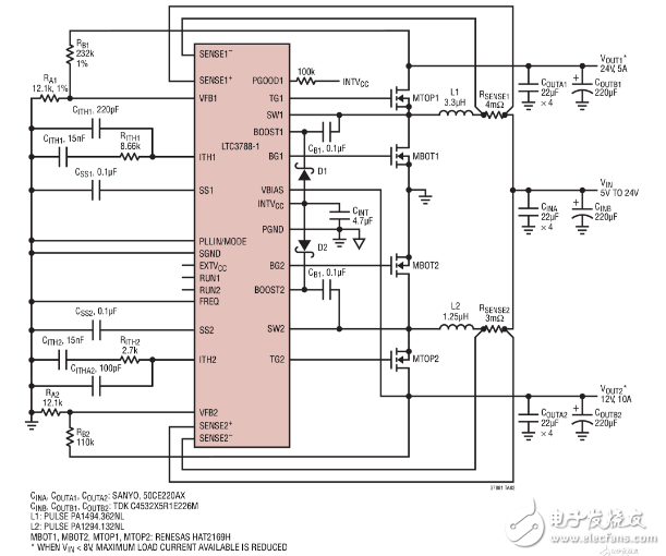
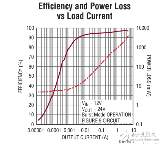
12v boost circuit diagram (3)The LTC3788-1 is a high performance, two phase, dual channel, synchronous boost converter controller for driving full N-channel power MOSFETs. Its synchronous rectification increases efficiency, reduces power loss, and reduces thermal requirements, allowing the LTC3788-1 to be used in high power boost applications.
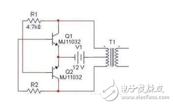
As shown in the figure below, we can also clearly see the required components and the connection between the various components. In addition to the transformer function, except for the transformer T1 for boosting and the power supply V1 for power supply, the remaining originals are rectangular. Wave circuit. In the choice of resistors, R1 and R2 are generally between 1.2k and 4.7k. There is no special requirement for the triode according to the capacity of the transformer. If the capacity is large, the power will be used. The transformer can be used as a normal control transformer. As long as there are two sets of 12V, we can In this schematic diagram, the selected device is transformer 0v-12V-12V, Darlington tube MJ11032 for triode, resistance 4.7k, output power can reach about 100W, not too small, but the power of the transformer should be selected. Otherwise the output power is not that big.
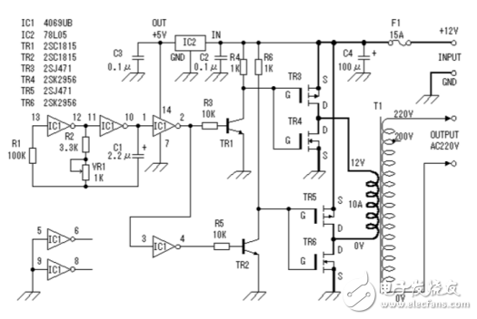
This inverter is mainly composed of a MOS field effect transistor and a common power transformer. Its output power depends on the power of the MOS FET and the power transformer.
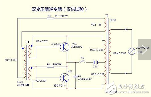
In the circuit diagram: 25T 310T 20T 250T is the winding turns of the transformer coil, VT1 is a high-power triode, can use the TV power supply tube, the resistance of R1 is 15-50Ω/5w, the resistance of R4 is 470Ω3W
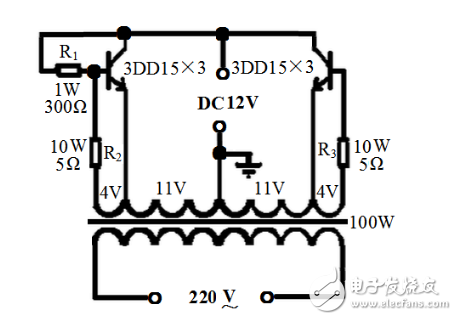
The transformer can be controlled by a 100W machine control transformer, the transformer core is taken apart, the secondary coil is removed, and the number of turns is recorded to calculate the number of turns per volt. Then rewind the secondary coil with a φ1.35mm enameled wire, first winding a 22V main coil, tapping in the middle, and then winding two 4V feedback coils with φ0.47 enameled wire. The layers of the coil are insulated with thick kraft paper. . After the coil is wound, the iron core is inserted, and the two 4V secondary wires are respectively connected with the main coil, and the end and the end are reversed. The voltage can be measured by the power. If the voltage increases after the connection between the 4V coil and the main coil, the connection is correct, and vice versa is wrong. You can change the connector.
Two resistors R2 and R3 connected in series with the 4V coil can be made of resistance wire. The size of the resistor can be selected according to the output power. Generally, it is several ohms. When the output power is large, the resistance is smaller. The bias resistor uses 1W300Ω resistor. The resistor can also work, but it is better to pick one because the parameters of the tube are inconsistent and sometimes not vibrating. Triode selection:
Use three 3DD15s in parallel on each side to share six pipes. After the circuit is connected, check that there is no error. Then you can adjust the power. Connect the battery, find a 100W incandescent lamp to load, turn on the switch, and the bulb should be able to illuminate normally. Can not normally emit light, can reduce the base resistance, until it can normally emit light, then connect to the color TV to see if it can start normally, can not start normally also reduce the base resistance, after the adjustment is completed, it can be used normally.
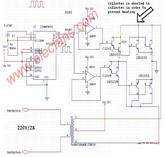
This DC 12V to 220V AC inverter circuit can be converted to 12V DC to 220V AC. CD4047 is used to generate square waves. The basic formula is P = VI between the input and output transformers, input power = output power. Therefore, the transformer is 12V to 220 volts, but the input winding must be able to withstand 20A.
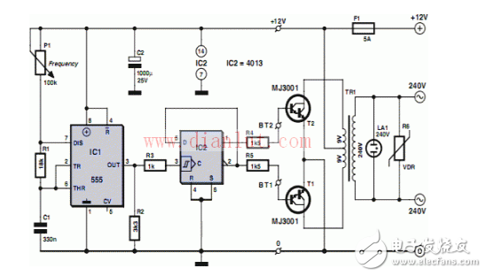
The 555 timer is a mid-scale integrated device that combines analog and digital functions. Generally known as 555 made by bipolar process, it is called 7555 in CMOS process. In addition to single timer, there is corresponding double timer 556/7556. 555 timer has wide power supply voltage range, which can be 4.5. Operating at V~16V, the 7555 can operate from 3 to 18V with an output drive current of approximately 200mA, so its output is compatible with TTL, CMOS or analog circuit levels.
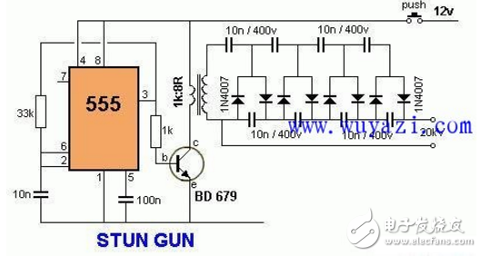
This circuit produces a very high voltage and must be used with care to prevent electric shock. The transformer can produce over 1000V and 8 stage voltage doublers and can produce up to 20KV DC high voltage.
Single Mining Power Supply 1800W
About this item
80 Plus Gold certified for lower power consumption, less noise and cooler temperaturesFor maximum cooling surface area and performance
Zero RPM fan mode for near silent operation at low to medium loads; Continuous output rated temperature: 50°C
100 percent industrial grade, 105°C rated Japanese capacitors ensure unwavering power and reliability
Fully modular cables, so you only connect the cables your system needs. Fan size-5.3 inches. iCUE Compatibility-No. Modern Standby Compatible- No
Features:
The power supply is 1800W conversion efficiency of 90+
Support graphics card 8, video card 6+2pin 16
Gold medal stability is strong
Gifts: power line 1:1 distribution
Voltage : 180v-220v 50Hz 10A
DC OUTPUT: 12V---150A MAX
POWER IN : 2000W MAX
Specification:
Name:Mine Chassis Power Supply
voltage : 180v-264v
Specifications
Color:black
PFC Type:active PFC
Power: max power 2000W
Appropriate Type:server MINING machine
power supply,mining power supply,power supply for mining,mining rig power supply,power supply for mining rig
Easy Electronic Technology Co.,Ltd , https://www.yxpcelectronicgroups.com