Synchronous generator data acquisition system based on ARM and ADE7758
This article introduces a new type of synchronous generator data acquisition system design scheme. The hardware design uses a 32-bit ARM micro-processor, and uses the energy-specific metering chip ADE7758 with a DSP core to replace the ordinary AD conversion chip. It is characterized by fast data collection speed, good real-time performance, and low price.
Data acquisition is one of the core units in the synchronous motor measurement and control system. At present, the data acquisition of synchronous generators is mostly based on general AD conversion chip with 8-bit or 16-bit single-chip microcomputer for AC sampling. This kind of data acquisition system obtains the generator operation The electrical parameters of the system are basically realized by software calculation, which not only has a large amount of calculation, low precision, and real-time performance is also greatly restricted. This paper proposes a high-precision, high-reliability, and fast data acquisition system composed of a dedicated electricity metering chip ADE7758 with a DSP core and a 32-bit ARM microprocessor with an ARM7 core for the above shortcomings.
1. The overall structure and working principle of the system
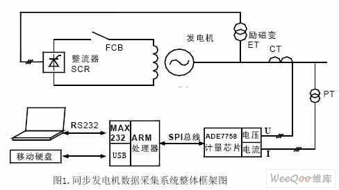
The overall structure diagram of the synchronous generator data acquisition system based on ARM and ADE7758 is shown in Figure 1 below. The working process of the data set is as follows: the measured signal, namely the terminal voltage U and the stator current I of the synchronous generator, are three-phase alternating currents, which are converted into low voltage and low voltage by a voltage transformer (PT) and a current transformer (CT), respectively. The secondary signal of the current is further processed by the signal conditioning circuit into a voltage signal of no more than 500mV and then sent to the metering chip ADE7758 for conversion. After the conversion of ADE7758 is completed, an interrupt request is submitted to the ARM processor. ARM corresponds to the ADE7758 interrupt request. The data in the corresponding buffer is read through the high-speed SPI interface, and then the actual value of the generator operating parameter is calculated according to the conversion ratio of the transformer and the transmitter. Save the result to the corresponding data area to prepare for real-time control of the generator. At the same time, the ARM processor communicates with the upper computer through the serial port, sends the latest collected generator operating parameters to the upper computer, and displays the real-time data using the upper computer software. The system is also designed with a USB interface, through which it can be connected to a mobile storage device, so that even if there is no computer, the task of data collection with a large amount of data can be achieved.
The ARM chip selected in this system is AT91SAM7A3. The communication between the AT91SAM7A3 chip and the metering dedicated chip ADE7758 uses a standard 3-wire high-speed SPI bus; the AT91SAM7A3 and the host computer are connected through a common twisted pair.
The communication is carried out in serial mode; AT91SAM7A3 and the mobile storage device are communicated with a USB interface.
2. System hardware design
This system chooses AT91SAM7A3 single-chip microcomputer as the main controller of the system, and the dedicated chip ADE7758 for electric energy measurement as the A/D conversion. The following is a detailed introduction to these two chips and the hardware circuit design centered on them.
2.1 Introduction to ADE7758
ADE7758 is a highly integrated three-phase energy dedicated metering chip. It integrates 6 second-order Sigma-Delta ADC sampling channels, with an SPI-compatible serial communication interface, and two pulse outputs. Using digital calibration technology, the chip setting, power data transmission and calibration can be completed through the standard SPI three-wire serial communication interface. ADE7758 integrates a temperature sensor inside, a single 5V power supply, low power consumption, suitable for three-phase three-wire and three-phase four-wire power systems [2].
The current channel and voltage channel of ADE7758 each have a programmable gain amplifier with a gain of 1, 2 or 4. In addition to the PGA function, it is also used for the selection of the full-scale range of the A/D conversion. The size of the gain is determined by user programming. ADE7758 has a waveform sampling register whose value is derived from the output of ADC. The waveform sampling part is integrated with a detection circuit for short-term continuous low or high level. The threshold level and duration are determined by user programming. The zero-crossing detection of any phase of the three-phase is carried out synchronously, and the result of the zero-crossing detection can be used to measure the period of any one of the three-way voltage inputs. All the functions of the ADE7758 are realized by reading and writing the internal registers of the ADE7758, that is, the various settings and operations of the ADE7758 are mainly the reading and writing of the registers. When each register is read and written, it is necessary to perform an operation of writing the communication register first, and then start to transmit data.
2.2 Introduction to AT91SAM7A3
AT91SAM7A3 microcontroller is an embedded 32-bit high-end microcontroller based on ARM7TDMI recently launched by ATMEL. This processor uses a high-density 16-bit instruction set to implement a 32-bit RISC structure, with low power consumption, short instruction execution cycle, fast running speed, and 32-bit multiplication and division instructions less than 1US. The AT91SAM7A3 microcontroller uses ATMEL’s high-density CMOS technology. It integrates ARM7TDMI and 256K Flash program memory, 32K on-chip SRAM and various peripheral function modules on a single chip, making it a powerful 32-bit micro Controller. The AT91SAM7A3 microcontroller has many internal working registers and rich on-chip peripherals. There are 62 multi-functional multiplexed I/0 ports and 3 Timer/counter modules on the chip. Each module contains 3 identical 16-bit timer/counters. Channels, each channel can be independently programmed to achieve various functions including frequency measurement, event counting, interval measurement, pulse generation delay and pulse width modulation, multiple interrupt sources, 8 interrupt priority levels, and 3 enhanced full Duplex USART, each USART has its own baud rate generator and two dedicated data controller PDC channels, 2 CAN controllers support CAN2.0B, 2 high-speed SPI, 1 I2C, 1 USB2. 0 interface, on-chip oscillator and watchdog circuit [1]. With 256k parallel programmable non-volatile FLASH program memory, it can realize serial in-system programming (ISP) (In-System Programming) of the device and in-application programming (IAP). Due to the abundant on-chip peripherals, it is convenient for system expansion, the on-chip storage capacity is large, and there is no need to expand the memory, which greatly improves the integration of the system, and provides a high degree of flexibility and cost-effective solutions for many embedded applications that require enhanced computing. .
2.3 System hardware connection
The hardware connection of the synchronous generator data acquisition system based on ARM and ADE7758 is shown in Figure 2. The hardware design of the system includes five parts: analog quantity acquisition module, signal conditioning module, AC power metering and conversion module, real-time data processing and control module, and display module.
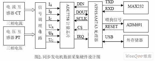
The acquisition of the on-site analog quantity of the synchronous generator is completed by CT and PT, that is, the generator terminal voltage and stator current are respectively converted into three-phase 100V, 5A secondary signals; the signal conditioning circuit completes the adjustment of the signal before entering the energy metering chip And filtering to filter out the high frequency part of the signal. The main purpose of this circuit module is to process the signal into a signal that ADE7758 can directly receive, that is, a voltage signal less than or equal to 500mV; the AC power metering and conversion module ADE7758 has voltage and current acquisition channels, The AC signal amplitude they can receive is up to 500mV, and they are digitized through 6 A/D sampling channels. The microprocessor in the ADE7758 performs various judgments, processing and calculations on the digitized signal under test, and stores the results in 18 read-only registers. ADE7758 submits an interrupt request to ARM after data conversion (IRQ is active low); the real-time data processing and control module is completed by the AT91SAM7A3 chip, and AT91SAM7A3 reads and writes the ADE7758 through the SPI interface, that is, the data of ARM and ADE7758 The interface adopts interrupt IRQ, chip select CS and 3-wire SPI interface to realize data exchange. The whole process can be described as: After the AT91SAM7A3 microprocessor responds to the interrupt of ADE7758, it immediately selects the CS of ADE7758 through the low-level chip, and then connects with the DIN, SCLK and DOUT of ADE7758 through the SPI bus MOSI, SCLK, MISO, and completes the data operation; The system display module circuit adopts MAXIM's MAX232 chip to complete the conversion between TTL level and RS-232 standard level, which is convenient for communication with the computer through the serial port.
In order to ensure the safety and reliability of the system, the watchdog in the ARM chip is not used in the system design, but an external watchdog circuit is specially designed. The external watchdog circuit adopts the ADM691 chip produced by AD company, and uses the pulse signal with adjustable duty cycle generated by the PWM port of AT91SAM7A3 as the feeding signal to monitor the power supply voltage and the working status of the microprocessor. The circuit has a simple structure and functions Abundant, greatly improving the safety and reliability of the system. On the other hand, in order to make the system have a certain wide range of usability, an interface supporting USB2.0 is also designed, the purpose is to facilitate a large amount of data collection without a computer.
3. System software design
The software design of the system includes two parts, the MCU program based on AT91SAM7A3 and the PC application program design.
3.1 AT91SAM7A3 MCU program design
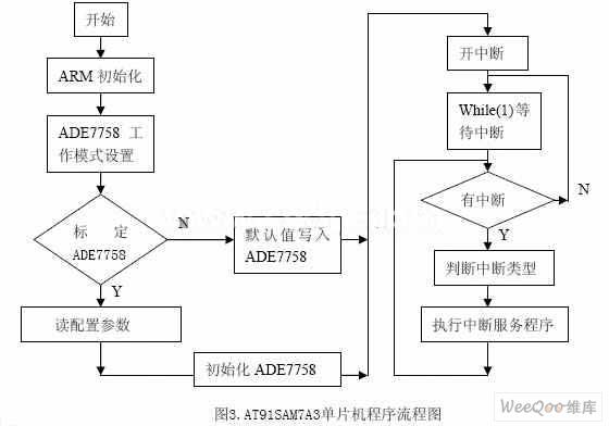
The program design block diagram taking AT91SAM7A3 one-chip computer as the core is shown as in Fig. 3. The judgment and processing of interrupts are the core part of the program. According to specific functional needs, interrupts include external interrupt IRQ0, timing interrupt and serial interrupt.
3.1.1 External interrupt IRQ0
The IRQ pin of ADE7758 is connected to the IRQ0 pin of the AT91SAM7A3 microcontroller. When the IRQ pin is set low, it means that the ADE7758 has an interrupt. The AT91SAM7A3 microcontroller uses the SPI port line to query the interrupt type. If it is a normal ADE7758 conversion end interrupt, the corresponding interrupt service subroutine is called Read the voltage, frequency and current values ​​in ADE7758.
3.1.2 Timed interrupt
There are 3 timer/counter modules inside the AT91SAM7A3 microcontroller. Each module contains 3 identical 16-bit timer/counter channels. Each channel can be independently programmed to achieve frequency measurement, event counting, interval measurement, and pulse generation delay. Various functions such as time and pulse width modulation. Here, timer 2 is used as a 1ms timer. When the interrupt is generated, the single-chip microcomputer reads the active power, reactive power and apparent power through the SPI port.
3.1.3 Serial interrupt
AT91SAM7A3 has a set of 32-bit serial port control registers. By setting the corresponding bits of each register, it is convenient to change the serial port operating mode, baud rate, parity, frame and overspeed of the single-chip microcomputer. This article uses an 8-bit UART with a baud rate of 19200 bit/s, ADE7758 calibration and three-phase current, voltage, active power, reactive power, apparent power, active electric energy, reactive electric energy, apparent electric energy, Power factor and other measurement data are packaged into serial communication messages and sent to the host computer in accordance with certain communication protocols.
3.2 Display of collected data
The upper computer program design is based on Visual Basic 6.0 as the platform [3], using MSComm control to realize serial communication between the computer and AT91SAM7A3 in an event-driven manner to complete data exchange. The upper computer program includes user interface design, communication and data processing programs.
3.2.1 Host computer user interface design
In this system, two forms (Form1 and Form2) are designed. Among them, Form1 is the main interface, which mainly displays real-time data and related state quantities. A MSComm control, two timer controls (Timer1, Timer2), two button controls (Command1, Command2) and a progress bar (ProgressBar) are designed in Form1. Command1 is the "send data" button, that is, when it is pressed, it will start communicating with AT91SAM7A3 to receive the recorded wave data. After successful reception, it will load Form2 and display the recorded wave curve. Command2 is the "Exit" button, press it to exit the application. Form2 is the waveform display operation interface. In Form2, in addition to designing a picture box control (Picture1) to display the graph curve, there are also 4 command buttons. They are the "Read File" button, the "Print Curve" button, and the "Print Curve" button. Coordinate modification" button and "return" button, among them, press the "return" button to return to the main interface.
3.2.1 Communication and data processing procedures
Set the Interval properties of Timer1 and Timer2 to be equal to 100, and Timer1 regularly extracts the data received from the serial port and refreshes the main interface to display the data in real time. Timer2 is used to control whether the communication is overtime, that is, if the serial port does not receive data within a certain period of time, it will prompt an error message. When Timer1 loads the main interface, Enable=True, at this time, Timer2's Enable=False, and Timer2, after pressing "Upload Data", Enable=True, then Timer1's Enable=False. The InputMode property of MSComm is 0, which means text mode. For the attribute value of RThreshold, it is set to 100 when receiving real-time data normally and 137 when receiving recorded wave data.
Below, the 10 data of three-phase voltage, current, active power, reactive power, apparent power and machine-side frequency at the generator terminal are taken as examples to illustrate the communication process. Each real-time data occupies 2 bytes, and the total amount of 10 integer data is 20 bytes. Converted to hexadecimal and sent a total of 40 bytes in text mode. The specific communication format of ARM and PC is:

The PC sends a transmission command to the lower computer ARM through the timer TIMER1 every 1 millisecond, and the command only contains a 2-byte start character
4. System operation and experimental results
Take Shenzhen Kaixuan K66 computer relay protection test system as the standard source to test and verify the voltage and current measurement accuracy of this system. When the input terminal voltage range is 0-100V, the measurement error is less than ±0.2%; when the input current range is 0-5A, the measurement error does not exceed ±0.4%. According to the technical conditions of the AC sampling remote control terminal, the accuracy level of this system is 0.5, which is a precision measuring instrument.
The author of this article is innovative: adopting the design ideas of new technology and new devices, replacing the general-purpose AD chip with the three-phase electric energy metering chip ADE7758, and replacing the ordinary 8-bit or 16-bit single-chip microcomputer with a 32-bit ARM chip, which realizes the power to the synchronous generator. Quick measurement and control of parameters. This system makes full use of the built-in functional modules of the chip, reduces the peripheral circuit, reduces the cost, and improves the reliability of the product.
24HR Electronic timer socket with photocell.
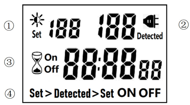
â‘ Light intensity setting
â‘¡ Light intensity detection
â‘¢ Countdown Timer ON & OFF
â‘£ 4 MODES:
Set > Detected: When the light intensity detection value is less than the set value, switch ON or OFF.
Detected > Set: When the light intensity detection value is greater than the set value, switch ON or OFF
ON : Always ON
OFF : Always OFF
NOTED:
1. The light intensity displayed by this machine is not the standard light intensity value (Lux), only the relative light intensity value.
2. The light intensity value is affected by the placement position and direction. Please determine the position first and then set it according to the actual light intensity detected. If you change the position or change the orientation, you need to reset the light intensity setting value suitable for the new position.
3. This product has built-in rechargeable battery. If it is not connected to AC for a long time, you need to connect the power supply to charge until the LCD can display normally.
MANUAL OPERATION
1. Press [UP" or [DOWN" to set the LUX value.
2. Press the [SET" key to start setting, and the P1 settable items will be flashed.
3. Press [UP" or [DOWN" to adjust the value.
4. Press [SET" key again to exit setting or enter next setting for countdown timer.
5. Repeat the [SET" key to start setting, and the P2 & P3 settable items will be flashed.


6. Press the [FUN" key to switch the working state in the following:
Set > Detected -> Detected > Set -> ON -> OFF
Set > Detected: Automatically switches when the detected ambient light intensity is darker than the set value
Detected >Set: Automatically switch when the detected ambient light intensity is brighter than the set value
When the brightness meets the setting conditions, the countdown starts as below:
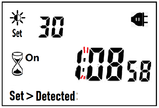
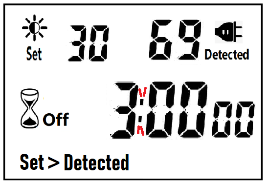
Note:when the countdown is ON, the detected value is not displayed.
When the brightness does not meet the setting conditions, the countdown stops and waits:
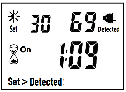
After the countdown ON is reduced to 0, the countdown OFF starts immediately and the power is OFF.
After the countdown OFF is reduced to 0:
A. If the light intensity meets the set conditions, a new round of countdown will be started;
B. If the light intensity does not meet the set conditions, keep the power off and wait for the light to meet the conditions before turning on automatically.
NOTE:
1. If the power is cut off while the countdown is running, the countdown will be terminated immediately and the relay output will be off. After the power is turned on again, a new round of brightness detection will start.
2. Modifying the brightness value in the countdown operation will not affect the current countdown operation. After the off time of the current countdown, the new brightness setting value will take effect.
3. In the countdown on operation, change the setting value of the countdown on, this countdown will still be timed according to the original setting value; the new setting value will take effect when the next countdown on starts.
4. In the countdown off operation, change the setting value of countdown off, this countdown will still be timed according to the original setting value; the new setting value will take effect when the next countdown off is started.
NOTE: the brightness setting value, countdown ON or countdown OFF, any one of which is equal to 0, cannot be switched ON or OFF automatically.
Manual Control
When ON or OFF is displayed, it means that the power supply remains ON or OFF, as shown in the figure below:

Power Detection and Standby Mode
With AC power supply, the icon ![]() lights up and works normally.
lights up and works normally.
When there is no AC power supply, the icon ![]() goes out, the brightness is not detected at this time, and the system enters the standby mode.
goes out, the brightness is not detected at this time, and the system enters the standby mode.
Photocell Timer, photocell timer socket, photocell sensor, photocell sensor socket, sensor plug, sensor switch socket, digital photocell timer, digital sensor timer
NINGBO COWELL ELECTRONICS & TECHNOLOGY CO., LTD , https://www.cowellsocket.com