Smartphone complex touch screen interface design
   Network-enabled multimedia smartphones have changed the way consumers use their phones. Of these phones, a particularly popular LCD touch screen interface allows users to use a variety of applications or scroll through web pages with their fingers. If you want to develop such complex interfaces without spending a lot of time, budget or power, it is an ideal choice for zero-power Altera MAX IIZ CPLDs.
Unlike ASSP or other competing technologies, MAX IIZ CPLDs have many I/Os, are easy to use, and have low power consumption, which can flexibly highlight product advantages. These advantages greatly simplify and accelerate the development of personalized handsets, portable media players and displays for medical, automotive and industrial applications. Altera's latest multi-touch screen reference design based on the MAX IIZ EPM240Z device helps designers quickly turn ideas into real-world products.
Custom or self-design
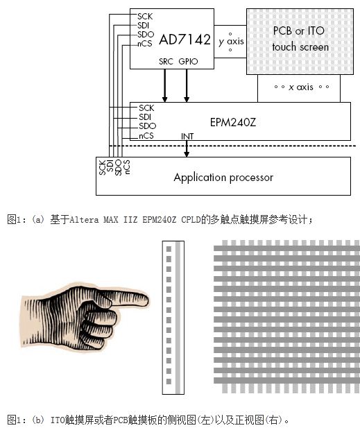
Any touch screen solution consists of two parts: a 2D touch sensor and a computing application that converts sensor data into user intent. The reference design is a complete sensor and data acquisition system that can be customized or used as is. It provides an indium tin oxide (ITO) screen and a simple double-sided PCB for use as a multi-contact navigation board. The 2D multi-contact reference design shown in Figure 1(a) is based on the MAX IIZ EPM240Z CPLD and ADI's AD7142 Integrated Capacitance-to-Digital Converter (CDC), which supports on-chip environmental calibration and ITO screens.
The reference design has a simple data interpretation program that demonstrates and tests the operation of the multi-contact sensor. The AD7142 CDC is used to monitor capacitance changes with only 14 capacitive sensor channels. In this reference design, the MAX IIZ CPLD extends the capabilities of the AD7142 CDC to handle two-dimensional ITO thin film and PCB touch sensors. The application processor accesses the CDC register file of the AD7142 through the SPI or I2C bus, and sets the SRC signal control of the MAX IIZ CPLD on the appropriate axis. After a long pause, the MAX IIZ CPLD generates an interrupt signal when the touch screen detects a touch.
ITO or PCB touch screen design
Any touch screen design starts with the actual touch sensor. Although this reference design is mainly for capacitive ITO touch screens, it is also applicable to double-sided PCBs with horizontal traces on one side and vertical traces on the other. The ITO touch screen has two transparent layers separated by insulators and 14 y traces. To the AD7142 CDC input, 16 x traces are connected to the MAX IIZ CPLD. The MAX IIZ CPLD adds more I/O, further increasing resolution and supporting a larger touch screen. The 14x16 design supports touch screens up to 16x14cm.

The ITO touch sensor has two mutually perpendicular layers separated by insulators, with x and y traces on top. Ideally, the x trace is below, the y trace is on top, and it is connected to the AD7142 input. The reason for this arrangement is that the CDC is more sensitive when monitoring the traces near the finger. The array of traces is wide with a pitch of 5 to 10 mm. The left side of Figure 1(b) is the intersection of the touch screen and the right side is the touch screen. In the actual display touch screen, the traces are transparent.
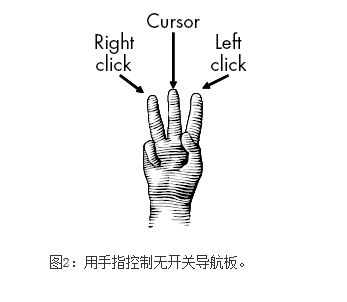
The sensor in Figure 1(b) enables the calculation of the navigation board, thereby avoiding the selection buttons required to use the normal navigation board. As shown in Figure 2, the middle finger moves the cursor, the index finger and the ring finger touch the screen, indicating the left mouse button or right click. Capacitive touch screen sensors are more durable than buttons and pushbutton switches when the moving part is removed.

ADI's AD7142 CDC
The AD7142 CDC is not designed to be used as a touch screen decoder, but to measure capacitance and capacitance variations of the sensor line array on the PCB. The AD7142 CDC has a complete electrical profile that calibrates a specific PCB layout and then measures capacitance for each of the 14 sensor inputs with an accuracy of 12 bits. These values ​​are accessed via the I2C or SPI bus after each measurement cycle. The AD7142 CDC sends a 250kHz square wave on the SRC signal, driving the traces close to the sensor board, and then measuring the received SRC signal strength. Since the touch screen capacitance is proportional to the received intensity of the SRC signal, the AD7142 CDC detects and quantifies the change in capacitance of the user's finger when it touches the touch screen.
AD7142 CDC
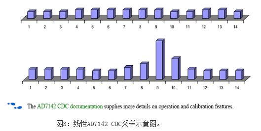
The AD7142 CDC performs 14 addressable capacitance measurements in succession. Figure 3 shows the register values ​​under baseline conditions when there is no finger contact, and the lower graph shows the register values ​​when the finger touches the sensor 9. The AD7142 CDC is very sensitive and the application processor uses this detailed capacitance vector value to determine that the finger is at the 9.3 sensor position, ie between sensors 9 and 10. The AD7142 CDC has an accuracy of 12 bits, so only 14 sensors are needed to accurately measure the position of the finger.

The AD7142 CDC document details the working process and calibration functions.
MAX IIZ CPLD converts linear sensors to 2D sensors
The AD7142 CDC measures the capacitance of 14 sensors relative to an SRC trace. After adding the MAX IIZ CPLD, the SRC square wave signal of the AD7142 CDC can be obtained under the control of the serial interface, and a vertical x trace of the touch screen can be selected to support multiple SRC traces. The AD7142 CDC can measure capacitance relative to a vertical trace or local. A large number of I/Os in the MAX IIZ (54 I/O in a 5x5mm package and 116 I/Os in a 7x7mm package) combined with the high-resolution capacitive digital measurement capability of the AD7142 make this solution suitable for larger areas. Touch screen and panel.
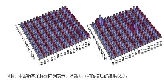
Figure 4 shows the 2D capacitance measurement results of the combination of the AD7142 CDC and the MAX IIZ CPLD, showing 16 traces, that is, 16 divisions of the x-axis. The left side is the baseline capacitance measurement, and the right side is the result of two fingers touching the sensor. The blue and red sample lines in the figure indicate which SRC trace is activated.

The application processor sets the MAX IIZ CPLD to drive the sensor S1 column and SRC signals through the serial interface and reads the 14 capacitor values ​​from the AD7142 CDC. The application processor then notifies the MAX IIZ CPLD to move the SRC to the next vertical trace and another 14 capacitance measurements, which are repeated until the application processor obtains all 244 (14x16) capacitance measurements in the 2D region of the touch sensor. . With the I2C bus, the time to acquire all data is approximately 375 ms, while the time to use the SPI bus is 300 ms. (Reducing the CDC sampling resolution reduces the sampling period). The application processor then processes the raw data to determine the user's intent.
Reduce power consumption, save time, and reduce processing
The MAX IIZ CPLD and AD7142 CDC touchscreen decoding reference designs are very efficient, typically requiring only 1.5mA at normal full speed operation and normal resolution. It also supports three other power levels. In the first low power stage, the application processor reduces the sample rate, collecting only a portion of the horizontal and vertical traces, or using the precise AD7142 CDC to determine the touch point between the traces. In the lower power stage, the user needs to touch the center of the screen to wake up the device, which requires the application processor to sample only one horizontal trace and one vertical trace.
The lowest power stage places the application processor and the AD7142 CDC in shutdown mode. With an external 32kHz clock and a sampling rate per second, the typical MAX IIZ CPLD standby current is only 50μA. When the MAX IIZ CPLD's high-efficiency capacitance detection system detects that the screen is touched, it wakes up the processor with an interrupt signal. After the processor wakes up, the system reads the touch location with greater precision.
Summary of this article
Single-touch screens and panels are no longer the latest means of implementing electronic system interfaces, but are considered essential features. Single-touch screen solutions have been widely used, so in order to make products favor consumers, two-point or multi-touch screens are needed. There are currently not many multi-contact solutions in use, and Altera MAX IIZ CPLDs enable flexible multi-contact user interfaces with existing components.
High Metering Current Transformer,Ct Transformer,Current Transducer,Rogowski Coil Current Sensor
IHUA INDUSTRIES CO.,LTD. , https://www.ihua-coil.com