Protect power and load through boost conversion phase
Output short-circuit faults, overloads, other faults, and high-capacitance loads at startup can severely damage or reduce input power and damage the load. The voltage requirements of the load itself may be very strict, and even higher voltages than the main input power supply are required. These conditions and requirements may cause the input power supply to be over-engineered or overburdened, especially when lifting the load. A common problem with boost converters for high voltage loads is that it provides a mechanism to protect downstream circuits. This is due to the fact that the inherent path from input to output exacerbates the pressure of the main supply and reduces the reliability of the system, especially under fault or overload conditions.
In some systems, the load requires an input voltage that is higher than the voltage that the main power supply can provide. One of them is the low-voltage battery-powered system. Industrial systems with fixed bus power (which can provide high efficiency power amplifiers for long cable and communication systems) often require a boost from a wide input voltage range DC/DC regulator.
Boost power supplies have some system advantages. In systems with large harnesses, high voltages can reduce the wire gauge required to deliver total power. By delving into the 48V battery, the automotive industry has been analyzing the problems associated with expensive and cumbersome cable connections. Systems with high power amplifiers, such as RF transmitters, are more efficient and have higher output power densities when using new transistors that operate from higher supply voltages. Some critical systems need to store energy through capacitive energy storage, which requires less capacitance at a higher voltage (E = 1/2*C*V2). The boost hold circuit can make the solution smaller in size.
Without considering the natural limitations of the boost converter, system reliability is reduced and costs are increased, which can lead to over-engineering of other components of the system. The boost circuit has a natural conduction path from input to output (Figure 1). Even if this converter is off, current can flow to the output through the body diode of the boost diode or synchronous power FET.
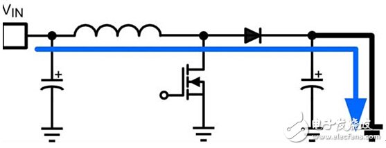
(a) Asynchronous boost 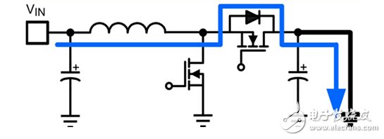
(b) Synchronous boost
If the load is a heavy capacitor, the mains supply or battery must be able to withstand the burden of the inrush current because the boost converter cannot provide any load isolation.
If there is no separate current limiting mechanism, the main power supply will be over-engineered. In systems such as alarm systems that require a backup battery, infinitely drawing current can affect the reliability of the battery, so the system may need a larger battery. Even the expected heavy load conditions can cause a circuit on the system voltage rail of a limited power source (such as a battery) to be powered down and an unexpected system restart. Modular systems powered by a common power bus are also at risk at startup. This power bus limits the number of modules that can be allowed based on the ability of the maximum supply current when there is no magnetizing inrush current limit or power sequencing.
A load fault can draw a strong current, such as a motor stall that occurs when an overload occurs. The solenoid used in the injector is another load that often has a short circuit fault. Pluggable modules with motors may require a boost voltage rail (provided by the main system) to save space and cost in a detachable assembly, but it is also possible to draw too much current from the main power supply in hot swap situations. An unprotected boost converter does not have the conditions to mitigate these risks; it simply passes these burdens to the power supply via the upstream circuit. Designers often solve this problem by over-engineering and over-utilizing the mains, but we can save system cost and increase reliability in the event of a boost load failure with simple limitations and protection techniques.
Protection method
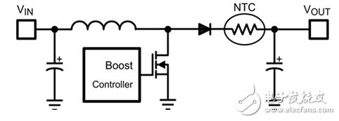
Figure 2. Passive magnetizing inrush current limit using an NTC thermistor.
The simplest current limiting mechanism is to use a negative temperature coefficient (NTC) thermistor (Figure 2). Due to the high impedance that occurs during cooling, the NTC limits the inrush current when starting up. The self-heating caused by its own power dissipation can lower the impedance and allow more current to flow. The advantage of this method is that it is simple and inexpensive. However, using this method under harsh conditions introduces certain disadvantages. For example, in an environment where the temperature of the engine compartment is greatly changed, there is a high ambient temperature that reduces the initial impedance of the NTC; in addition, if the entire environmental operating conditions are not carefully managed, excessive magnetizing inrush current is caused. In the event of a restart, the NTC device temperature may not have cooled before the next power up. When the output capacitor is completely discharged, the NTC limits the magnetizing inrush current to a minimum due to the slower heat dissipation rate. In addition, if a short-circuit fault occurs in the load, the NTC will not be able to limit the supply current that is higher than the selected nominal operating conditions. Finally, the NTC method is effective for single function protection, but this method is subject to certain limitations due to the use of passive components.
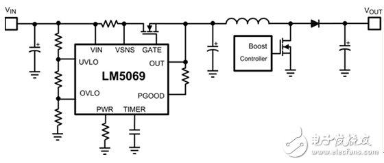
Figure 3. Active magnetizing inrush current limit using hot swap.
Selecting an active limiting device such as a MOSFET requires a control circuit for the inrush current limiting controller, also known as a hot swap controller or electronic fuse. This is an additional integrated circuit (IC) in front of the boost controller. Many of these controllers (Figure 3) feature programmable inrush limits including current and voltage loops to ensure that the MOSFET remains in the safety group. While in the zone (SOA), the influx rate is controlled. SOA is used to monitor the long-term reliability of critical protection devices. In addition, the inrush controller has two current thresholds: one for regulating the inrush limit and the second for completing the breaker function in severe overcurrent conditions. A clear advantage of this approach is that you can achieve its advanced protection features; however, in general, this solution is more costly and complex than passive methods.
The third protection option is a boost controller with integrated inrush limit control. This method still requires an additional MOSFET to be used as a protection device because the boosted high-side component (a freewheeling diode or synchronous MOSFET) cannot be inverted. However, as shown in Figure 4, integrating boost and protection control in an IC helps reduce solution complexity and size compared to hot-swap controller methods, while also providing many other protection features.
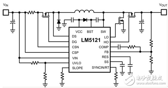
Figure 4. Boost controller that supports integrated magnetizing inrush current limiting.
Power Plugs Crimping Machine,Two Prong Power Strip,Wall Socket Extension Cord,Two Prong Power Cord
Kunshan Bolun Automation Equipment Co., Ltd , https://www1.bolunmachinery.com