How to use network single chip W7100A to realize TCP communication?
Today I will introduce how to implement TCP communication in the application note of the Ethernet control network microcontroller W7100A.
TCP (Transmission Control Protocol) is a protocol for controlling data communication between networks. As one of the main protocols that make up the Internet, more detailed content has been written in RFC 793 of the IETF (Internet Engineering Task Force). TCP is a protocol running on the IP layer, which ensures the effective transmission of data and can be received in sequence according to the data sending order.
Because the W7100A microcontroller supports the TCP protocol at the transport layer, users can directly use the TCP / IP protocol without any integration.
I will explain to you one by one.
1 TCP SOCKET
Users can use the TCP protocol in all 8 SOCKETs provided by W7100A, but they must first create the SOCKET to be used. When creating SOCKET, you need to use the SOCKET number, protocol, port number and flag. This document will introduce what is the TCP protocol and how to set Sn_MR (SOCKET n mode register in the TCPIP core) to Sn_MR_TCP (0 & TImes; 01) when using the TCP protocol. The SOCKET number means that the user can choose any of the eight SOCKETs from 0 to 7. The port number indicates the port specified by the user under the TCP protocol. If all of the above requirements have been set, then the socket () function can be assigned to create a SOCKET.
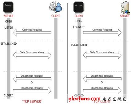
Since the TCP protocol of the W7100A microcontroller supports server mode and client mode, users can choose a mode to achieve this application. The difference between server mode and client mode is shown in the figure below:

<Figure 1.1> TCP server and TCP client
As shown in Figure 1.1, the process of TCP server mode and client mode is roughly the same. The only difference is whether SOCKET status is listening or connected after opening SOCKET. When the TCP protocol is running in server mode, the server is in a listening state waiting for connection requests from clients. If the TCP protocol is running in client mode, the client will request to connect to the server in the connected state. Once the connection is successfully established, the state of SOCKET will become established (SOCK_ESTABLISHED, 0 & TImes; 17). SOCKET can still maintain the connection state after the point-to-point connection is established, so as to exchange data until SOCKET is closed.
The SOCKET cycle in server mode consists of opening, listening, sending, receiving, disconnecting and closing. The SOCKET cycle in client mode consists of opening, connecting, sending, receiving, disconnecting, and closing.
1.1 Open (OPEN)
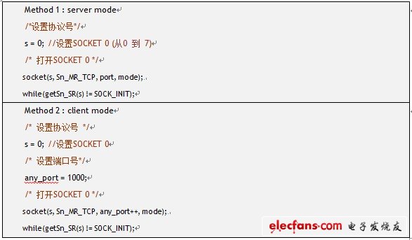
Whether in server mode or client mode, the first step in creating SOCKET is to open SOCKET. Use the SOCKET () function to set the SOCKET number, protocol, port number, and flag to create a SOCKETn (take the n-1th SOCKET value). Since the TCP protocol is used, the protocol needs to be set to Sn_MR_TCP (0 & TImes; 01). The setting of the port number depends on whether it is in server mode or client mode. If it is in server mode, the server will set the source port number according to the port used by the current user. However, if it is in client mode, because the destination port number is being used, it is best to randomly select a port number and increase a number each time until SOCKET is connected. The flag bit of the TCP protocol means 'no delay confirmation flag bit'. Generally speaking, set this bit to 0. More information about protocol types, flags, etc. will be introduced in 'Sn_MR value' under the 'TCPIPCore.h' file.
After all the settings are completed, check whether the state of SOCKETn becomes SOCK_INIT (0 & TImes; 13) by checking the Sn_SR (n) register. The user can complete the check process of the Sn_SR (N) register through the getSn_SR (SOCKETn) function. If the status of SOCKET is SOCK_INIT (0 × 13), it means that SOCKET was created successfully; if it is not successful, the user needs to recreate SOCKET.

Example 1.1 Open SOCKET
Marine Overflow Observation Alarm
The utility model has a simple structure. When the tank overflows, the overflow medium flows into the oil tank through the oil inlet pipe, and flows into the lower part of the oil tank through the gap between the baffle plate and the oil tank. When the overflow medium is higher than the oil inlet of the oil overflow pipe, When the float floats, the float signal switch on the alarm is triggered to realize the overflow alarm.
marine overflow observation alarm,marine overflow observation alarm price,overflow observation alarm
Taizhou Jiabo Instrument Technology Co., Ltd. , https://www.taizhoujiabo.com