How to detect strain-type load cell failure
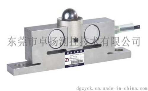
Introduction: Resistance strain-type load cells have been widely used in the field of electronic weighing, automatic control and automatic detection. It is an electromechanical component that converts force signals into electrical signals, and is also a core component of weighing and detection systems. . Its definition, composition and working principle are as follows:

Definition: A force sensor that measures the mass by converting one of the measured (mass) into another measured (output) after taking into account the effects of the gravitational acceleration (g) and the air buoyancy (f) of the place of use.
Measured (mass) Load cell output
Composition: Sensing element + sensing element + measuring circuit
Among them: sensitive elements - elastomers; sensing elements - resistance strain gauges; measuring circuits - Wheatstone bridge
Working principle: Resistance strain gauge with metal material as conversion element, its conversion principle is based on the resistance of the metal resistance wire - strain effect. The so-called strain effect refers to a physical phenomenon in which the resistance value of a metal conductor (resistance wire) changes with deformation (elongation or shortening).
It is not difficult to imagine after understanding the above composition and principle: The resistance strain sensor failure is often due to some artificial or natural damage, such as sensor overload, shock, or accidentally dropped, strong sensor wire, lightning or high current through the sensor, chemical corrosion , Moisture erosion or high dust environment and the aging of components inside the sensor. The direct consequence may be a drift in the weighing system, an unstable display or no display of data. The following section mainly introduces the detection methods and steps of the sensor in some common faults of the weighing system for our customers to refer to in practice.
First of all, before you remove the load cell from the weighing system, you should carefully and judiciously determine whether the system structure and the sensor have the following problems:
1) Check whether it is a system transmission failure, which may be due to dust, mechanical misalignment, delayed transmission of components, etc., rather than sensor failure;
2) Check whether the system has any damage, rust or obvious wear in the force transmission part. In winter, whether the sensor is in the force transfer position is icing phenomenon, affecting the transmission and resetting of the system;
3) Check whether the limit device of the system is working and whether the clearance meets the requirements;
4) Check whether the connection between the sensor cable and the junction box and display meter is correct, whether there is a disconnection or poor connection of the connection wire; check the connection reliability of the bus nine-pin plug and junction box;
5) Check whether the junction box and the instrument are faulty, especially the situation of the potentiometer and the connection terminal in the junction box;
6) Check whether the sensor is rusty and damp (especially the patch hole area); the integrity of the sensor cable; the environment of the sensor cable entrance.
It is recommended that the user is equipped with the following instrumentation as a necessary device for detecting the sensor:
A) High-performance calibrated digital multimeter (more than four and a half digits), inspection accuracy can reach ± ​​0.1Ω and ± 0.01mv, check sensor zero output and bridge integrity;
B) Megohmmeter (insulation meter), test the insulation resistance of the sensor. It is recommended to test 5000MΩ at 50VDC.
General sensor manufacturers should be produced in accordance with relevant technical standards. The detailed technical performance data of the product provides detailed input/output impedance, insulation resistance, zero output, and output sensitivity on the certificate accompanying the product. Correct wiring code identification, etc.
Special recommendation: The sensor company should analyze and feedback the sensor returned by the user more quickly and accurately, and it should require the extensive cooperation of the users. It is recommended to record the fault condition you encountered on the site in detail by following the form, with the product or Fax directly to the sensor company for symptomatic analysis and feedback improvement measures. Provide the following sample for your reference. At the same time, weighing companies should also check the status of service personnel through this form to record certain checks.
The first step: zero output check
Zero output, which is the output value of the sensor in the absence of load, and the output of all sensors (including the static body of the scale body, transfer force, etc.) must be tested. The zero point of the sensor should be tested under the condition that the sensor is designed, installed and used to prevent the erroneous influence brought by the weight of the sensor itself. The sensor should be connected to a regulated power supply, preferably using the product instructions or the excitation voltage recommended in the sample. The millivolt voltage output of the test sensor is divided by the sensor's excitation voltage to give the sensor's zero output value (mV/V). Comparing this output value with the value on the sensor's certificate (if possible) or with the corresponding data in the sensor company's sample, it can be concluded that the zero output of the sensor is acceptable.
Analysis: Permanent changes in the sensor's zero position are generally due to sensor overload or transient shocks. However, if the sensor's zero periodic variation may be due to moisture in the strain gage or internal changes due to other reasons, of course, this condition can also be detected by detecting the insulation resistance of the sensor and testing the bridge resistance.
Step 2: Test insulation resistance
In general, we are required to test the impedance between the sensor lead and the sensor body (elastomer, housing, etc.). Note that the sensor is disconnected from the junction box and the meter. Debug the insulation test box (table), and then connect the end of the test lead to the cable of the sensor (output, input, shielded wire, etc.), and connect the end of the test lead to the body of the sensor (elastomer, housing, etc.). General requirements, the impedance ≥ 5000MΩ.
Note: It is not allowed to test the input and output impedance of the sensor with the test pen of the insulation box, because the output voltage of the insulation box is higher than the withstand voltage value of the internal electrical components of the sensor.
Analysis: We generally require that the insulation resistance between the sensor lead and the elastomer be ≥ 5000 MΩ. The low insulation value may be due to moisture in the sensor bridge or damage to the local bridge. A particularly low insulation resistance (≤1KΩ) may be due to the fact that the sensor is seriously affected by moisture and the short circuit between the bridge circuit and the elastomer or the breakdown of the internal wiring insulation layer is damaged. The direct manifestation of low sensor insulation is that the sensor output is not stable, and will change with changes in environmental conditions, or even interfere with the printer's operation.
Step 3: Test Bridge Impedance
Testing bridge impedance is to detect the integrity of the sensor bridge. When testing, the sensor should be disconnected from the junction box and other test equipment. The input and output impedance test is to measure the impedance value at the input end and output end of the sensor with a digital multimeter test pen, and to compare the test value with the product's certificate; the confirmation of bridge symmetry refers to the use of a digital multimeter. Taking the impedance between one input and the same output, the four impedance values ​​can be obtained by successive measurement. In a fully symmetrically compensated sensor, the extreme values ​​of the four impedance values ​​must not exceed 1 Ω (the low-precision multimeter has this value. Must not be larger than 2Ω).
Analysis: Changes in bridge impedance are often due to broken or broken bridges, failure of electronic components or internal short circuits. This may be due to high current or voltage (lightning strikes or welding currents) puncturing burned bridges, or due to shock or vibration fatigue, or ultra-high temperatures.
Step 4: Test Sensor Output
Connect the sensor to the regulated power supply separately and use the excitation voltage 10-15VDC. Connect the output end of the sensor to the millivoltmeter (or put the multimeter in the DC millivolt range) and load the load end of the sensor based on the sensor's installation status. Observe the changes in the sensor output.
Analysis: Under normal circumstances, the sensor should have a positive output. If the output of the sensor is abnormal, it may be due to sensor wiring errors or the sensor strain gauge and the elastomer matrix falling off, internal disconnection, etc.
About the Sensor Inspection The document provides the customer with a sensor checklist intended to guide our users in the detection of the sensor. The quality analysis personnel of the sensor company can judge the content of the fault in the use of the user according to the content, thereby providing targeted guidance and assistance for the use of the user; at the same time, the sensor company can provide the information provided by the user according to the information provided by the user. A purposeful determination is made to increase the pertinence of the analysis and the efficiency of the analysis and speed up the information feedback.
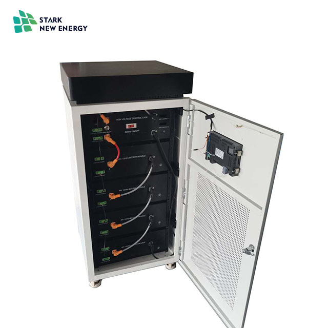
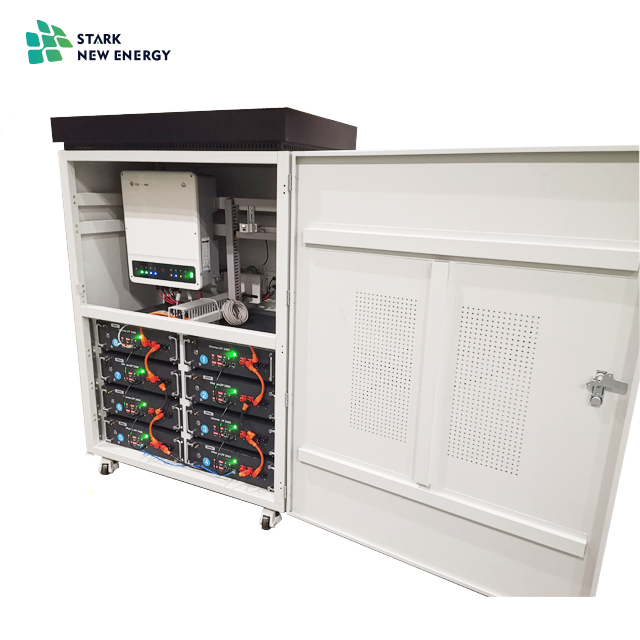
Jiangsu Stark New Energy was founded in 2018. It is an emerging new energy manufacturer and trader. Our company focuses on the integration and research and development of household energy storage systems. The Energy Storage System integrates our company`s lithium iron phosphate battery packs. 48V 51.2V batteries are connected in series and parallel to meet the requirements for battery voltage and capacity.
Equipped with a dedicated inverter control all-in-one machine for home connected and off-grid energy storage, it realizes the free switching of energy between photovoltaic mains and batteries, making energy more efficient, and allowing many islands and other areas with no electricity or unstable mains to obtain Reliable power supply
At present, our best-selling products include 10KWH 5KW and 20KWH 10KW energy storage all-in-one machines, which can also be customized according to the specific needs of customers to fully meet the needs of customers and the market.


Home Energy Storage System,Energy Storage System Lithium Battery,Solar Energt Storage Battery System,Hybrid Energy Storage System
Jiangsu Stark New Energy Co.,Ltd , https://www.stark-newenergy.com