How to communicate between PC and MCU? These methods are taken away.
In order to realize the mutual communication between the PC and the multiple MCUs, especially when multiple MCUs need to transmit data to the PC, the research group adopts the "point-name" bus control method. After obtaining the "name" command sent by the PC, the MCU starts to control the bus and transmit data to the PC. After the data transfer is completed, the PC is notified and the bus control is exited, and the PC transmits the "name" command one by one. According to this idea, the corresponding circuit is built. After continuous experiment, debugging and improvement, the constructed system works stably and reliably. The "point-and-click" multi-machine interworking mode is very suitable for occasions where multiple MCUs are required to transmit data to a PC, which has high practical value.
0 Preface
The master-slave system consisting of a PC and a single-chip microcomputer is very common and has been applied in many fields. In these systems, serial communication is generally used between the PC and the MCU. Data and instructions are exchanged according to a certain format, and the PC control of the MCU, data forwarding, or data and status on the MCU are completed. Return.
When the number of microcontrollers is large, it is easier to control the PC to all microcontrollers. Generally in this case, the broadcast method is adopted.
All the MCUs are hung on a serial data bus, only need to address the MCU, and the PC broadcasts the address data and the control message. After receiving the broadcast data, the MCU performs address comparison and filters out the required data. The corresponding data transfer.
If the PC wants to broadcast to the MCU and return all the information of the MCU, that is, the MCU needs to send data to the PC, plus the number of MCUs is larger (more than 100 MCUs), then the PC and MCU should be realized. The difficulty of communicating with each other is relatively large.
This paper proposes a practical method, through the actual circuit construction and debugging, realizes the mutual communication between PC and MCU, and achieves the predetermined goal, so that the system has the following functions:
(1) The PC can control all 100 MCUs, and send different control words to each MCU as needed;
(2) The state modification of the PC to the MCU is random and irregular;
(3) All the MCUs return some of their status information to the PC in order.
1 Several ways to achieve mutual communication
The broadcast from PC to multiple MCUs is relatively simple. It is more difficult for multiple MCUs to send data to the PC. Since more than 100 single-chip microcomputers are hung on one data bus, the difficulty of system design lies in the transmission of control rights of the data bus. It is absolutely impossible for two or more devices to send data to the bus at the same time. At the beginning of the system design, two kinds of bus control methods were considered: relay type and point name type:
(1) Relay bus control mode
The basic idea of ​​this control method is: after initialization, all the MCUs are in the serial receiving state after receiving the PC data, and do not occupy the bus control right. The PC sends a loopback start command, the first microcontroller responds to the command, and immediately takes control of the bus, and sends data to the PC on the bus. After the data transmission is completed, the first microcontroller sends a control command to notify the second. The single-chip microcomputer, at the same time, the first single-chip microcomputer exits the bus control right and is in the receiving state; after receiving the first instruction of the first single-chip microcomputer, the second single-chip microcomputer starts transmitting data to the bus, and ends the transmission, like the first single-chip microcomputer. After that, the third MCU is notified, and thus, the relay is continuously transmitted, and the bus is controlled in turn until the last MCU completes the data transmission. In the process of controlling the bus and transmitting back in the single-chip microcomputer, if the data is to be transmitted to a certain or some single-chip microcomputer through the PC, the PC software will automatically store the data, and wait until the last one-chip computer receives the data sent to the PC. The PC then takes up the data bus and starts transmitting data to the microcontroller.
(2) Named bus control mode
The control method is basically the same as the relay control method. The difference is that this control method needs to wait for the PC to name the command. After the system is initialized, after the MCU receives the PC command and data, the PC sends the point name command, so that the first MCU starts to transmit data. After receiving the instruction, the first MCU immediately takes up the bus and starts transmitting data. After the transmission is finished, the transmission is sent. After the end instruction is sent to the PC, the PC immediately occupies the bus after receiving the end instruction, and then sends the name command, so that the second MCU starts to transmit data, so that the operation continues until the last MCU ends the transmission.
When the MCU transmits data, if the PC wants to send data to the MCU, after receiving the MCU data, it can suspend the sending of the name command and directly send the data to one or some MCUs. After the data transmission is completed, continue to connect the sequence number of the original interrupt, and continue to name and transfer the data. Considering these two kinds of bus control methods, it is not difficult to find that the relay transmission efficiency is slightly higher than the point name because there is no instruction time overhead for transferring the name to and from the point. Therefore, the relay control method is adopted at the beginning.
But when it comes to large system joint debugging, the problem arises. Due to the process intervention of the relay-type off-the-PC, once a single-chip program runs and crashes, the entire program cannot proceed, and it is in a waiting state, and the whole system is paralyzed. There have been several crashes during the debugging process. Finally, I had to go back and modify the overall plan, using a point-based control. If there is an abnormality in one of the MCUs, and the data is not returned according to the predetermined program, the PC can judge the MCU crash. After experiencing a waiting time, skip the MCU and name the next MCU to continue the subsequent process. Transmission and procedures. If the faulty microcontroller is still occupying the bus and affects the operation of the next single-chip microcomputer, an overall reset signal is sent to the reset terminal common to the single-chip microcomputer, so that all the single-chip microcomputers are reset. After re-adjustment, after a long period of operation, there was no crash of the whole machine, and the overall operation was good. In addition, this control method has the advantages that the other two control methods do not have:
This function can be very useful by interrupting the return at any time and sending new instructions to some or some of the microcontrollers almost in real time.
2 system hardware composition
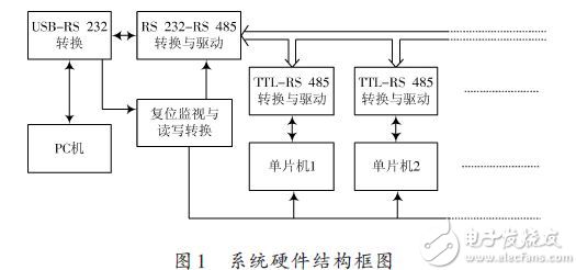
According to the overall requirements of the system, the hardware platform shown in Figure 1 is constructed.

The whole system adopts RS 485 bus structure, RS 485 is differential balanced digital communication mode, with strong anti-interference ability, widely used in long-distance digital communication. The biggest difference between RS 485 and RS 422A bus is that RS 485 can be transmitted in simplex and bidirectional, while RS 422A can only transmit data in one direction. In this system, if there are a large number of single-chip microcomputers, if RS 422A is used, the cable will double. In addition, since the standard RS 485 link can only connect 32 devices, the driver is added to each converter. At present, it is difficult to find the serial port on the PC, so the PL2303 chip is used for bridging between the PC and the RS 485 bus. The PL2303 is a Prolific product that can easily convert a USB interface to a standard RS 232 level. Users don't have to worry about complex USB protocols and specifications at all. In PC-side software programming, you only need to use a USB port like a standard com port. Because of the driver provided by Prolific, the USB port has been simulated as a standard com port. The chip's maximum speed can reach 115 200 b / s, which greatly facilitates the communication between ordinary serial communication and PC. The reset monitor and read/write conversion circuit is also a single-chip microcomputer, but the microcontroller only performs two functions. One is to receive the signal from the PC TXD (TXD of RS 232) before receiving the RS 485 bus. Once the global reset serial code from the PC is generated, a global reset signal is generated to reset all the microcontrollers. This function is to prevent a single-chip microcomputer from malfunctioning and has been accidentally occupying the bus, causing the entire system to crash.
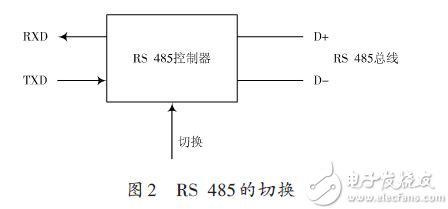
In order to achieve half-duplex communication of RS 485, there must be a direction switching control signal, as shown in Figure 2. In the MCU end, this control signal is easy to obtain, and an I/O pin is derived, which can control the switching of the signal in the MCU program; however, the RS 485 switching on the PC side is relatively troublesome, which is also reset monitoring and reading and writing. Another important feature of the conversion circuit: read-write conversion. If the PC wants to occupy the RS 485 bus, it sends a specific serial code. The dedicated MCU receives and responds to the serial code, switches the RS 485 controller, starts to occupy the 485 bus and sends data. If the PC ends sending data, Then send a specific serial code at the same time, notify the dedicated microcontroller, and perform the corresponding RS 485 switch. The microcontroller and its associated circuits form the relevant functional circuits.

The main MCU adopts the 8051F020 enhanced MCU of Silicon Company. The biggest advantage of this MCU is that the integrated analog circuit function is more powerful, the MCU runs fast, and the program writing-programming-simulation is more convenient.
3 system software composition
The software is divided into three parts: PC host computer program, single-chip general-purpose program and special-purpose single-chip program. The program of the special-purpose single-chip microcomputer runs in the reset monitoring and reading-and-writing conversion circuit. The program is relatively simple, that is, after power-on, the serial data sent by the PC is always received according to the agreed baud rate and data format, and if the obtained data meets The agreed reset format sends a reset signal; if the received data conforms to the bus switch format, the corresponding switch signal is sent. The PC host computer program is more complicated, and the related application program can be written according to the actual needs of the user. In this paper, the application program is written in Delphi, which realizes the parameter setting, state adjustment, information feedback and system control of the single-chip microcomputer group.
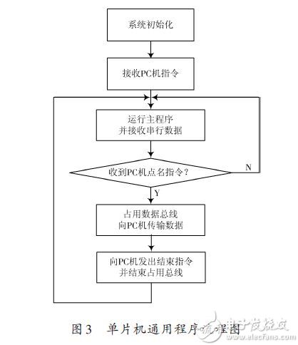
The general-purpose program of the single-chip microcomputer runs on more than 100 single-chip microcomputers respectively, which is the basis for realizing the system functions. Figure 3 is a flow chart of the microcontroller program.

After the MCU is initialized, it receives the initial instruction sent by the PC, and then starts running the main program to execute the main function of the MCU. At the same time, the serial receiving interrupt is opened. Once the command sent from the PC is received, the comparison judgment is made. If the PC is pointing to its own name, it responds to the PC's loopback command, starts to occupy the bus, and transmits data to the PC. The end PC sends the end status word, ends the occupation of the bus, returns to the main program, and waits for the serial data to be received.
4 Conclusion
After a lot of experiments, the research group applied the point-name bus control method, successfully solved the problem of bidirectional intercommunication between PC and a large number of single-chip microcomputers, realized the mutual communication between more than 100 single-chip computers and the main control PC, and achieved the design requirements. The circuit has been running for a long time, and the actual situation shows that the system is stable in operation, flexible in control, high in reliability, and the point-name bus control method adopted has good practical value.
Wi-Fi Internet access can be simply understood as wireless Internet access. Almost all smart phones, tablets and laptops support Wi-Fi Internet access, which is the most widely used wireless network transmission technology today. In fact, it is to convert the wired network signal into a wireless signal, just like the introduction to everyone at the beginning, use a wireless router for the relevant computers, mobile phones, tablets, etc. that support its technology to receive. If the mobile phone has Wi-Fi function, when there is Wi-Fi wireless signal, it can go online without going through the network of China Unicom, saving the data charge.
Wireless network wireless Internet access is more commonly used in big cities. Although the wireless communication quality transmitted by Wi-Fi technology is not very good, the data security performance is worse than Bluetooth, and the transmission quality needs to be improved, but the transmission speed is very fast, which can reach 54Mbps. Personal and social information needs. The main advantage of Wi-Fi is that it does not require wiring and can not be restricted by wiring conditions, so it is very suitable for the needs of mobile office users, and because the transmit signal power is less than 100mw, which is lower than the mobile phone transmit power, Wi-Fi Internet access is relatively It is also the safest and most healthy.
However, the Wi-Fi signal is also provided by the wired network, such as the ADSL at home, the broadband of the residential area, etc. As long as a wireless router is connected, the wired signal can be converted into a Wi-Fi signal. Many cities in developed countries abroad are covered with Wi-Fi signals provided by the government or large companies for residents to use. There are also many places in my country that implement "wireless city" projects to promote this technology. In pilot cities where 4G licenses have not been issued, many places use 4G to Wi-Fi for citizens to try.
XPON WIFI ONU, GEPON WIFI ONU, XPON Router ONU,WIFI ONU XPON, ONU XPON WIFI
Shenzhen GL-COM Technology CO.,LTD. , https://www.szglcom.com