How to choose the optimal Buck converter topology?
Summary
The basic Buck converter topology is the same, but there are many ways to control the converter's operation, and different methods bring different characteristics. Correspondingly, the load characteristics in reality are also different. How do you map different converter topologies to different applications? Understand the basic characteristics and limitations of various topologies and understand your application requirements. This is the basic condition for achieving the right choice.
I. Overview
The basic Buck converter topology is this:

Figure 1. Basic topology of the Buck converter
In this topology, the high-side power switch S1 and the low-end power switch S2 are turned on in turn, and the chopper signal thus formed is filtered by the inductor L and the output capacitor COUT to form an output voltage, and the output voltage VOUT is controlled by the S1 conduction time. The duty cycle is determined.
A complete Buck system needs to detect certain signals to determine how to control the duty cycle of the switch, and the feedback signals available in the circuit as a Buck control system are varied to control the duty cycle of the switch. There are also many methods. Real-world loads also have their own unique personality, and they have different characteristics for the Buck converters that power them, which leads to the emergence of various control architectures.
There are many different types of Buck converters in the DC/DC product catalog, which use different control architectures. The most traditional are the Current Mode (CM) and Constant-On-TIme (COT) modes, as well as the current mode constant on-time (Current Mode Constant-On-TIme). , CMCOT) mode, and improved Advanced Constant-On-TIme (ACOTTM) mode. These different control architectures are implemented differently, each with different characteristics, and their advantages and limitations are also different.
Faced with such a large number of control architectures, how should we choose the right architecture for our application needs? Let us start with understanding.
Second, current mode (Current Mode, CM)
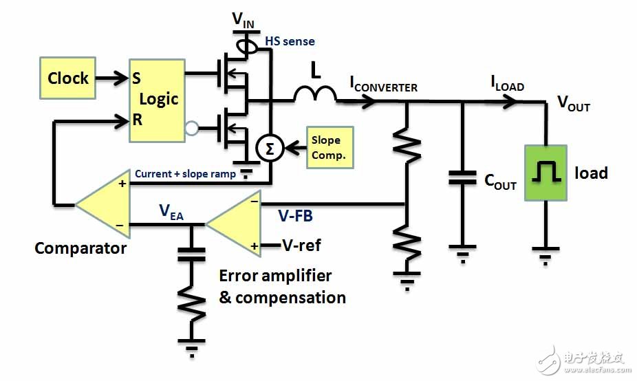
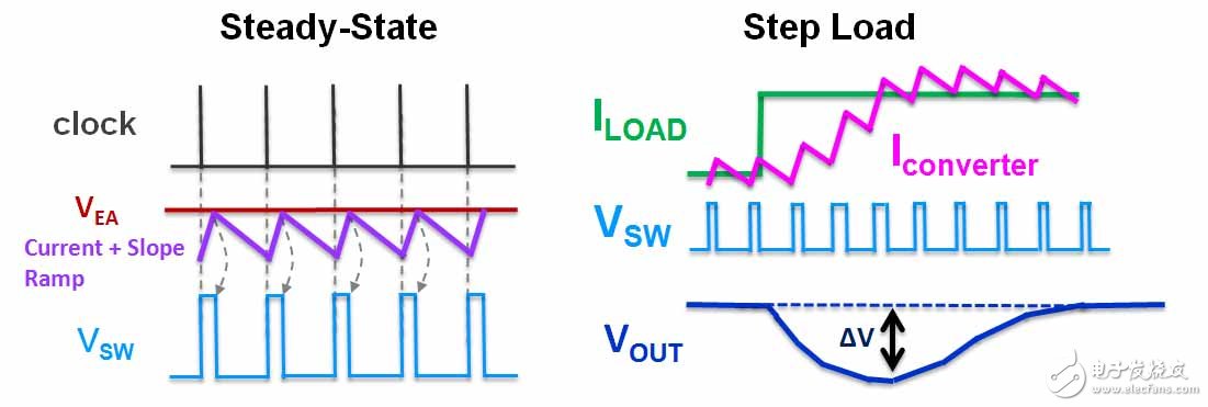
The most traditional current mode Buck converter controls the output voltage by controlling the on-time of the MOSFET power switch. It has a fixed-frequency internal clock that controls the rhythm of the switch. The decision-making time for the on-time is derived from the inductor. The comparison result of the peak current detection signal and the error amplifier. The following is a schematic diagram of its circuit topology and its corresponding waveform:

Figure 2. Current Mode Buck Converter Circuit Topology 
Figure 3. Operating waveform of the current mode Buck converter
The bandwidth of the control loop of this architecture is set by the error amplifier and is typically limited to levels that are much smaller than the switching switching operating frequency.
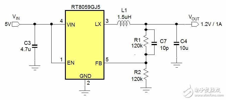
The RT8059 is a TSOT-23-5 current mode Buck converter with a maximum operating voltage of 5.5V, an output current capability of 1A, and operates at a fixed frequency of 1.5MHz. This is its application circuit diagram:

Figure 4. Circuit example of current mode Buck converter
---------------------------
More power technology hot text can pay attention to the latest issue of the "Power Technology Special Issue" released by the electronic enthusiast network .

Y10T Isotropic Ferrite Magnet,Anisotropic Ferrite Magnet y35, Motor Rotor Ferrite Magnet
HU NAN YUBANG MAGNETIC MATERIAL CO.,LTD , https://www.ybmagnet.com