Home gateway system based on ARM and Clinux
This article uses ARM core 32-bit embedded microprocessor as the hardware platform, combined with wireless communication technology, realizes a convenient by transplanting embedded operating system mClinux, and developing corresponding drivers, applications and embedded Web server on it. A practical home gateway.
This article refers to the address: http://
System hardware design
System structure and working principle
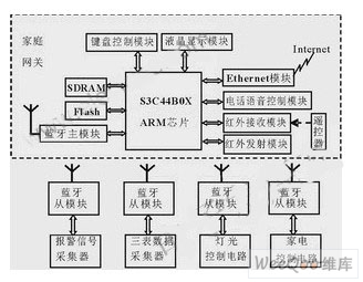
The system structure of the home gateway is shown in Figure 1. It is based on Samsung's 32-bit RISC processor S3C44B0X, through external memory (Flash / SDRAM), Bluetooth module, LCD screen, keypad, Ethernet interface module, The telephone voice control module and the infrared transceiver module are used to construct a hardware platform, and various control modes can be implemented.

Figure 1 Home Gateway System Structure
1) Local keyboard and display control: The system is equipped with 16 buttons and a 128×32 dot matrix liquid crystal display, which is convenient for users to set and query the status locally, such as data query and electrical control.
2) Local infrared remote control: Through the infrared remote control module with self-learning function, infrared remote control of indoor appliances can be realized.
3) Remote telephone voice control: This is a telephone remote control based on the Public Switched Telephone Network (PSTN) for command control of telephones, such as remote control of home appliances, telephone alarms, etc.
4) Internet-based remote control: using browser-side/server-side structure (B/S structure), users can directly use Windows' own IE browser as a client program to achieve remote control anytime, anywhere.
Wireless communication technology is the most ideal technology for home networking, which eliminates the hassle of rewiring within the home. In the design of the home gateway, the Bluetooth module is used as a wireless communication module to communicate with each of the underlying functional modules.
Hardware circuit composition
The hardware design of this system mainly includes the basic hardware platform built with S3C44B0X embedded microprocessor as the core, as well as the hardware design of modules such as Bluetooth communication, telephone voice control and infrared remote control.
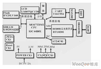
The hardware block diagram of the basic hardware platform with S3C44B0X as the core is shown in Figure 2. The functions and interface circuits of each part are analyzed as follows.

Figure 2 Block diagram of the basic hardware platform of the home gateway
ARM Microprocessor S3C44B0X: S3C44B0X is the SoC of ARM7 core produced by Samsung. It is suitable for handheld devices and common embedded applications by extending a series of complete general peripheral devices based on ARM7TDMI content.
Flash memory interface circuit: The Flash chip is used to store the embedded operating system in the home gateway, the home network server, the CGI gateway application, and the file system required to support various services. A 16-bit Flash memory system is built in the system using a HY29LV160 with a storage capacity of 2MB. After the system is powered on or reset, the instruction is fetched and execution begins, so the flash memory is configured to ROM/SRAM/FLASH Bank0.
SDRAM interface circuit: The existence of embedded operating system requires a certain amount of dynamic RAM. The decompressed operating system will move from Flash to SDRAM and reside in memory. At the same time, the user stack and running data will also be placed in SDRAM. The 8K cache provided by the S3C44B0X chip is far from satisfactory. Taking into account the needs of the actual application, Samsung's K4S281632D was chosen in the design. Its data width is 16 bits, consisting of 4 banks and a storage capacity of 16 MB. Bank6 and Bank7 of S3C44B0X support SDRAM, so it is easy to connect. Set the data width of Bank6 to 16 bits in the bus width control register BWSCON. Set MT = 0x3, Trcd = 0x0, SCAN = 0x01 in the Bank6 control register BANKCON6, and set BK76MAP = 0x110 in the storage capacity register BANKSIZE.
10/100M Ethernet interface circuit: The S3C44B0X internally includes Ethernet MAC control, but does not provide a physical layer interface. Therefore, an external physical layer chip is required to provide an Ethernet access channel. The RTL8201 was chosen for this design. Since the S3C44B0X has a MAC controller with an MII interface on the chip, and the RTL8201 also provides an MII interface, the definition of various signals is also very clear. Therefore, the connection between the RTL8201 and the S3C44B0X is relatively simple, and only two chips are required for connection. The corresponding pins can be interconnected. It is worth noting that the RTL8201 using CMOS technology cannot be directly connected to the RJ45 interface. Due to the difference of level signals and the existence of network impact signals, components that need isolation and level signal conversion between the two, the network is selected in this design. Transformer HR61H58L.
Serial interface circuit: In order to complete the communication with the Bluetooth communication module, infrared transmitting and receiving module and telephone voice control module of the home internal network, the home gateway needs to have an asynchronous serial communication interface. Since the S3C44B0X has only two asynchronous serial ports, it needs to be The serial port is extended. In this design, a ST16C554 chip is selected for serial port expansion. Since the high and low level signals defined by the LVTTL circuit of the S3C44B0X system are different from the high and low level signals defined by the RS-232-C standard, communication between the two must be converted by the signal level. Here, the MAX202 is used to convert the serial data signal into a TTL level, and then the ST16C554 outputs an interrupt request. The interrupt request of the four serial ports is ORed to generate the IRQ signal INTREQ, which is connected to the terminal controller of the CPU via the CPLD.
IIC interface circuit: S3C44B0X contains an IIC bus master, which can be easily connected to various devices with IIC interface. In this system, an AT24C01 is externally expanded as an IIC memory. The AT24C01 provides 128 bytes of EEPROM memory space, which can be used to store a small amount of data that needs to be saved when the system is powered down, such as the parameter settings of the home gateway and the user authentication code.
LCD display module: This module can be used by Sharp Corporation's LM057QC1T01, which is a graphic dot matrix 256-color STN liquid crystal module with a resolution of 320×240. Because the S3C44B0X and LM057QC1T01 are highly versatile, they are easy to connect, but a circuit that implements voltage deflection is required between the controller and the LCD interface to achieve the 27V deflection voltage required for outputting the LCD display.
Keyboard interface circuit: 4 x 4 keyboards are composed of 8 general purpose I/O ports.
Other peripheral circuits required by the S3C44B0X: JTAG interface circuit (for JTAG debug), reset circuit, and power supply circuit.
Other function module Bluetooth module: In this solution, the Bluetooth hardware chip adopts the ROK 101008 module of Ericsson. The home gateway adopts the method of installing BlueZ under the Clinux operating system to cooperate with the Bluetooth module, and establishing a related protocol based on the L2CAP layer.
Telephone voice control module: The dual-tone dialing chip DTMF8870, voice synthesis chip ISD1420, ringing current detection chip circuit and 89C51 are used to form a telephone voice control module.
Infrared remote control module: The infrared receiving module and infrared transmitting module are added to the system. The infrared receiving module selects BA5302, the infrared signal is input from the top, and after being amplified, shaped and demodulated, it is converted into a digital signal of TTL level; the infrared transmitting module modulates and transmits the infrared original code just learned. Here, a software-encoded method is used to generate a modulated signal, so the circuit is simple.
System software platform
Establishing the Clinux development environment The application development environment based on the Clinux operating system is generally composed of the target system hardware development board (the development board of the S3C44B0X) and the host PC. The kernel compilation, application development and debugging of the operating system used by the target board need to be completed by the host PC. The connection relationship between the two is generally established through a serial port, a parallel port or an Ethernet interface. First, to install a standard Linux operating system on the host, you can then establish a cross-development environment. Download the toolchain from the web and install the cross compiler on the host. Also reconfigure, compile the kernel according to the needs of the home gateway, and carry out mClinux porting. After success, you can see two kernel files in the mClinux-Samsung/images directory: image.ram and image.rom. Write image.rom to the flash memory corresponding to ROM/SRAM/FLASH Bank0. When the system is reset or powered on, the kernel will self-extract to SDRAM and start running. Such an embedded application development platform has been successfully built.
Hardware driver and application development
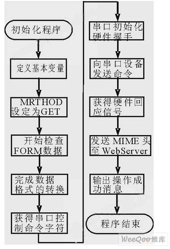
Hardware driver and application development should also be carried out in a cross-compilation environment, first developed on a PC, then ported to the target machine for debugging and finally solidified to the target machine. The hardware drivers that need to be developed in this design are: Ethernet card controller, serial port, LCD driver, Bluetooth module, keypad driver, etc. Writing drivers for the Linux kernel is not as complicated as other operating systems. Just write a few basic functions for the corresponding device and register with VFS. Generally, it is based on a ready-made driver for specific hardware devices. Changes. On the basis of the embedded operating system, it is necessary to develop a micro GUI, write dynamic web pages and CGI programs to implement embedded WEB technology, security authentication, and wireless communication protocols. For example, the remote control based on the Internet is realized by browsing the dynamic webpage of the Web Server in the home gateway, and the remote control program needs to extract useful control command information from the user access information, and then compose the command frame according to the internal protocol of the home control network. The key to achieving control is the compilation of CGI programs. The process is shown in Figure 3.

Figure 3 Internet remote control program flow diagram
Conclusion
This paper discusses the hardware and software design of a wireless home gateway based on ARM microprocessor S3C44B0X and mClinux. The home gateway has various control modes, and can remotely control home appliances by browsing the webpage anytime and anywhere. The home gateway is low in cost, easy to upgrade, and easy to promote and apply.
A Hose Reel is a cylindrical spindle made of either metal, fiberglass, or plastic and is used for storing a hose. The most common styles of hose reels are spring driven (which is self retracting), hand crank, or motor driven. Hose reels are categorized by the diameter and length of the hose they hold, the pressure rating and the rewind method. Hose reels can either be fixed in a permanent location, or portable and attached to a truck, trailer, or cart.
Automatic hose reels for diesel and oil have been designed to ensure highefficiency.
The sturdy structure can guarantee best performance also in heavy duty conditions.
Thanks to its high volume design, this retractable diesel fuel hose reel is capable of dealing with environments where a longer length hose is required
Hose Reel
Hose Reel,Air Hose Reel,Water Hose Reel,Oil Hose Reel
NINGBO BEILUN TIAOYUE MACHINE CO., LTD. , http://www.spool-manufacturer.com