Hall sensor working principle, detection method, characteristic parameters and its advantages
The Hall sensor is a magnetic sensor based on the Hall effect. The object with current is placed in the magnetic field. If the current direction and the direction of the magnetic field are perpendicular to each other, a lateral potential difference is generated in a direction perpendicular to both the magnetic field and the current direction. This phenomenon is called a Hall effect, and the generated potential difference is called Hall voltage. A Hall device is fabricated using a semiconductor material that produces a significant Hall effect. As a magnetoelectric conversion element in a Hall sensor, electromagnetic measurement can be performed, such as measuring magnetic physical quantities and electric quantities such as magnetic field, current, and electric power. Hall sensors can also use the magnetic field as a medium to achieve non-contact measurement for many physical quantities. By measuring the non-electricity such as force, displacement, vibration, acceleration, speed, flow, etc., it is widely used in industry, transportation, communication, automatic control, home. Electrical appliances and other fields.

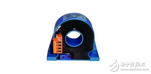
The Hall current sensor is fabricated according to the Hall principle. It works in two ways, magnetic balance and straight. The Hall current sensor generally consists of a primary circuit, a magnetic flux ring, a Hall device, a (secondary coil), and an amplifying circuit.
Direct current sensor (open loop)
It is well known that when a current passes through a long wire, a magnetic field is generated around the wire. The magnitude of this magnetic field is proportional to the current flowing through the wire. It can be induced by the core to the Hall device and has a signal. Output. This signal is amplified by the signal amplifier and output directly.
The rated output is calibrated to 4V.
Magnetic balance current sensor (closed loop)
The magnetic balance type current sensor is also called a compensation type sensor, that is, the magnetic field generated by the main circuit measured current Ip at the collecting magnetic ring is compensated by a magnetic field generated by the current through a secondary coil, so that the Hall device is in detecting the zero magnetic flux. Working status.
The specific working process of the magnetic balance current sensor is: when a current flows through the main circuit, the magnetic field generated on the wire is collected by the collecting ring and sensed on the Hall device, and the generated signal output is used to drive the corresponding power tube and Turn it on to obtain a compensation current Is. This current then generates a magnetic field through the multi-turn winding, which is exactly opposite to the magnetic field generated by the current being measured, thus compensating the original magnetic field and causing the loss of the Hall device.
It gradually decreases. When the magnetic field generated by multiplying Ip and the number of turns is equal, Is no longer increases. At this time, the Hall device functions to indicate zero magnetic flux, and can be balanced by Is at this time. Any change in the measured current will destroy this balance. Once the magnetic field is out of balance, the Hall device has a signal output. Immediately after power amplification, a corresponding current flows through the secondary winding to compensate for the unbalanced magnetic field. From the imbalance of the magnetic field to the rebalancing, the time required is theoretically less than 1 μs, which is a process of dynamic equilibrium.
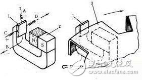
There is a Hall semiconductor chip in the magnetic field through which the constant current I passes from A to B. Under the action of Lorentz force, the electron flow of I shifts to one side when passing through the Hall semiconductor, causing the sheet to generate a potential difference in the CD direction, which is called a Hall voltage.
The Hall voltage changes with the change of the magnetic field strength. The stronger the magnetic field, the higher the voltage, the weaker the magnetic field, the lower the voltage, the smaller the Hall voltage, usually only a few millivolts, but amplified by the amplifier in the integrated circuit. This voltage can be amplified enough to output a stronger signal. If the Hall IC is used for sensing, a mechanical method is required to change the magnetic induction. The method shown in the figure below uses a rotating impeller as a switch to control the magnetic flux. When the impeller blades are in the air gap between the magnet and the Hall IC, the magnetic field deviates from the integrated piece and the Hall voltage disappears. Thus, the change of the output voltage of the Hall integrated circuit can indicate a certain position of the impeller drive shaft. With this working principle, the Hall IC can be used as the ignition timing sensor. The Hall effect sensor is a passive sensor that requires an external power supply to operate. This feature allows it to detect low speed operation.

1-Hall Semiconductor Component 2 - Permanent Magnet 3 - Barrier Magnetic Line Blade
Main characteristic parameters of Hall sensorAs mentioned above, the Hall sensor is a magnetic field sensor fabricated according to the Hall effect. Its main characteristic parameters are as follows.
(1) Input resistance R
The DC resistance of the two excitation current terminals of the Hall sensor element is called an input resistance. Its value ranges from a few euros to a hundred euros, depending on the components of the different models.
As the temperature rises, the input resistance becomes smaller, which causes the input current to become larger, eventually causing the Hall sensor potential to change. In order to reduce this effect, it is preferable to use a constant current source as an excitation source.
(2) Output resistance R
The resistance between the potential outputs of the two Hall sensors is called the output resistance, and its digits are of the same order of magnitude as the input resistance. It also changes with temperature changes. Choosing the appropriate load resistor is easy to match to minimize the drift of the temperature-induced water potential.
(3) Maximum excitation current I---Hall sensor parameters
Since the potential of the Hall sensor increases with the increase of the excitation current, it is always desirable to select a larger excitation current of 1 M in the application but the excitation current is increased, the power consumption of the component is increased, and the temperature of the component is increased. As a result, the temperature drift of the Hall sensor's potential increases, so each of the models specifies a corresponding maximum excitation current, which ranges from a few milliamps to hundreds of milliamps.
(4) Sensitivity K
Sensitivity KH = EH / IB, its value is about 10MV (MA.T).
(5) Maximum magnetic induction BM---Hall sensor parameters
When the magnetic induction exceeds BM, the nonlinear error of the Hall sensor potential will increase significantly, and Tes(T) becomes several thousand Gauss (Gs) (1Gs = 104T).
(6) an equipotential potential
At the rated excitation current F, when the applied magnetic field is zero, it is an error due to the asymmetry of the geometry of the four dipoles.
(7) Hall sensor potential temperature coefficient
The value of 6M is generally zero. The open circuit voltage between the output terminals of the Hall sensor is called the unequal potential. When using the bridge method, the bridge method is used to compensate the unequal potential, which is caused by a certain magnetic induction intensity and excitation current. When the temperature changes by 1 degree Celsius, the percentage change of the Hall sensor potential is weakly the Hall sensor potential temperature coefficient, which is related to the material of the Hall sensor element.

The current sensor is an electrical component that detects the current of the power line. The output signal is sent to other execution circuits according to different needs, and further displays the current value and controls other electrical appliances.
Current sensor main characteristic parameters
1, standard rating and rated output current
The size of the standard rating is related to the model number of the sensor product. Current sensor rated output current, generally 10~400mA.
2, offset current
The offset current is also called residual current or residual current, which is mainly caused by the unstable operation state of the operational amplifier in the Hall element or the electronic circuit.
3, linearity
The linearity determines the extent to which the sensor output signal (secondary current IS) is proportional to the input signal (primary current IP) within the measurement range.
4, temperature drift
5, overload
The overload capability of the current sensor means that when a current overload occurs, the primary current will increase outside the measurement range, and the duration of the overload current may be short, and the overload value may exceed the allowable value of the sensor. The overload current value sensor Generally not measured, but it will not damage the sensor.
6, accuracy
The accuracy of the current sensor depends on the standard rated current. The effects of offset current, linearity, and temperature drift must also be considered when assessing sensor accuracy.
If you are a user, pay attention to the specifications and models.

In many applications in scientific experiments and industrial applications, current and voltage measurements and control are required, especially in cases where high current and high voltage measurements and controls are required and the current and voltage requirements are high. It is necessary to use a current-voltage sensor that is safe, convenient, reliable, and highly accurate. In the early days, shunts and voltage dividers were used to detect current and voltage. However, this method cannot measure the main circuit in isolation. This method is unsafe and has low accuracy. Later, people invented the transformer. Compared with the method of direct shunting and voltage division, it realizes the isolation detection of the main loop, which is undoubtedly a big progress, but its application range is narrow, only suitable for 50Hz sine wave work. Frequency detection, it can't do anything for other waveform current and voltage measurements.
With the development of power electronics technology, the original current detecting components (such as shunts, transformers) can not meet the medium, high frequency, high di / dt, wide spectrum current waveform transmission, Hall current voltage sensor is to make up for this A vacant, main detection component with a wide range of applications and prospects. Compared with common transformers, Hall current and voltage sensors have the following characteristics:
1. Wide measurement range: It can measure the current and voltage of arbitrary waveforms, such as DC, AC, pulse, triangle waveform, etc., and even faithfully reflect transient peak current and voltage signals;
2. Fast response: The fastest response time is only 1us.
3. High measurement accuracy: its measurement accuracy is better than 1%, which is suitable for the measurement of any waveform. The common transformer is an inductive component that affects the waveform of the signal under test after being connected. Its general accuracy is 3%~5%, and it is only suitable for 50Hz sinusoidal waveform.
4. Good linearity: better than 0.2%
5. Good dynamic performance: fast response time, less than 1us; common transformer response time is 10~20ms.
6. Working frequency bandwidth: Signals in the frequency range of 0~100KHz can be measured.
7. High reliability, average trouble-free working time: average time between failures, 5 10 hours
8. Strong overload capability and large measuring range: 0---tens of amps to tens of amps
9. Small size, light weight and easy to install.
Due to the advantages of Hall current and voltage sensors, it can be widely used with variable frequency speed control devices, inverter devices, UPS power supplies, inverter welding machines, electrolytic plating, CNC machine tools, microcomputer monitoring systems, power grid monitoring systems, and isolation detection currents. In various fields of voltage. Hall devices have many advantages, they are solid in structure, small in size, light in weight, long in life, easy to install, low in power consumption, high in frequency (up to 1 MHZ), resistant to vibration, not afraid of dust, oil, water vapor and salt spray. Contaminated or corroded.
The Hall linear device has high precision and good linearity; the Hall switch device has no contact, no wear, clear output waveform, no jitter, no rebound, and high position repeatability (up to μm level). Hall devices with various compensation and protection measures have a wide operating temperature range of -55 ° C to 150 ° C.
According to the nature of the objects being detected, their applications can be divided into direct applications and indirect applications. The former directly detects the magnetic field or magnetic characteristics of the object to be inspected, and the latter detects the artificially set magnetic field on the object to be used, and uses this magnetic field as a carrier for the detected information, through which many non-electrical and non-magnetic materials are used. Physical quantities such as force, moment, pressure, stress, position, displacement, velocity, acceleration, angle, angular velocity, number of revolutions, rotational speed, and time at which the operating state changes are converted into electrical quantities for detection and control.
Displacement measurement
The two permanent magnets are placed opposite each other with the same polarity. The linear Hall sensor is placed in the middle, and the magnetic induction intensity is zero. This point can be used as the zero point of the displacement. When the Hall sensor is â–³Z displacement on the Z axis, the sensor has A voltage output whose voltage is proportional to the magnitude of the displacement.
Force measurement
If the parameters such as tension and pressure are changed into displacements, the force and pressure can be measured, and the force sensor can be made according to this principle.
Angular velocity measurement
A magnetic steel is adhered to the edge of the disc of the non-magnetic material, the Hall sensor is placed near the edge of the disc, and the disc rotates once, and the Hall sensor outputs a pulse, so that the number of revolutions (counter) can be measured. By entering the frequency meter, the speed can be measured.
Line speed measurement
If the switch-type Hall sensor is regularly arranged on the track at a predetermined position, a pulse signal can be measured from the measuring circuit when a permanent magnet mounted on the moving vehicle passes through it. The speed of movement of the vehicle can be measured based on the distribution of the pulse signal.
LEME Heat- Not- Burning Cigarette
Shenzhen Esun Herb Co.,Ltd. , https://www.szyoutai-tech.com