Detailed explanation: Capacitive MEMS microphone readout circuit design
1 Introduction
Compared with the traditional electret condenser microphone, the capacitive MEMS microphone has the following advantages: 1) stable performance, low temperature coefficient, low influence by humidity and mechanical vibration; 2) low cost; 3) compact size, capacitive The back plate and diaphragm of the MEMS microphone are only about 1/10 of the smallest electret condenser microphone; 4) the power consumption is lower. The advantages of the above aspects make capacitive MEMS microphones more and more widely used.
However, capacitive MEMS microphones also present challenges for designers: 1) the small signal amplitude generated by the microphone under the action of sound pressure is very small, requiring the noise of the readout circuit to be extremely low; 2) the static capacitance of the capacitive MEMS microphone is pF On the order of magnitude, the readout circuit requires an input resistor of the order of GΩ to achieve a high-pass filter with a pole frequency below 20 Hz. Therefore, the implementation of a high-resistance resistor is another challenge for the readout circuit; 3) The capacitive MEMS microphone is usually applied. For battery-powered products, low-power design is also a constraint that must be considered when reading out circuit designs.
Based on the above considerations, based on the analysis of the working principle of capacitive MEMS microphone, a low-power, low-noise, high-resolution capacitive MEMS microphone readout circuit is proposed.
2 capacitive MEMS microphone
2.1 Working principle
The main structure of a capacitive MEMS microphone consists of a thin, flexible acoustic diaphragm and a rigid back plate. The diaphragm, the back plate and the air gap between them form a parallel plate capacitor, so:
V=Q/C, C=εS/x (1)
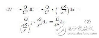
Where C is the capacitance, S is the area of ​​the plate, Q is the amount of charge stored when the voltage between the plates is V, ε is the dielectric constant of the medium (air) between the plates, and x is between the plates distance. When the sound pressure change of the dP size acts on the diaphragm, it will cause a voltage change between the two plates:

Since dxâˆdP, the output voltage dVâˆdP. This is the principle of acoustic-electric conversion of a capacitive MEMS microphone.
The condition for this principle is established: in the process of acoustic-electrical conversion, it is necessary to keep the charge Q stored in the microphone capacitor constant, so it is necessary to add a stable DC voltage to charge the capacitor to maintain a constant state of charge. This function is implemented by a charge pump.
2.2 Microphone readout circuit structure
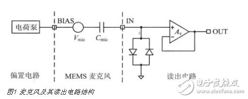
The system consisting of a capacitive MEMS microphone and its readout circuit is shown in Figure 1.

The charge pump provides a stable DC voltage to the microphone to keep the amount of charge stored in the microphone capacitor constant. On this basis, when the sound pressure acts on the diaphragm, it will cause a change in the voltage between the two poles of the microphone. The voltage small signal Vmic in this audio range is high-pass filtered by the microphone capacitor Cmic and the high-resistance input resistance of the readout circuit. Read out.
It is important to note that the back-to-back diodes serve three purposes: 1) providing a high-impedance input resistor, a high-pass filter with a low-pole frequency with the microphone capacitor, and thus a small signal reading of the microphone; 2) providing a unity-gain buffer DC bias voltage; 3) Static protection, providing a low-resistance DC path when the readout circuit is subjected to electrostatic attack. The function of the unity gain buffer is to shield the microphone and the subsequent signal processing circuit to avoid mutual influence between the two, and to improve the driving capability of the readout circuit.
Fargo Cleaning Card,Fargo Printer Cleaning Card,Fargo 82133 Cleaning Cards,Fargo Cleaning Kit
Miraclean Technology Co., Ltd. , https://www.mrccleanroom.com