Design high-performance USB devices with Artix-7 FPGAs
Author: Tom Myers Senior Hardware Engineer, Anritsu Company tom.
Low-power Xilinx FPGA family makes bus-powered USB devices easy to design
With billions of ports in the market, Universal Serial Bus (USB) is the interface of choice for connections below gigabit between host and peripheral. However, because the USB specification has strict inrush current and steady-state operating current limit requirements, bus-powered device applications often ignore FPGAs, preferring to use microcontroller solutions that are less powerful and less flexible than FPGAs.
With the advent of the newest member of the Xilinx low-power family of devices, ArTIx-7, this situation will no longer exist. By paying close attention to system-level power conversion efficiency and sequencing, and using power estimation and optimization tools in the VivadoDesign Suite, designers can overcome these challenging limitations to achieve high-performance, tightly integrated, bus-powered custom devices.
Let's take a look at how to build a bus-powered USB 2.0 high-speed device based on the ArTIx-7 MicroBlaze platform. At Anritsu, we successfully developed a new microwave power measurement product using this solution. The new product is designed with a USB 2.0 high-speed interface that significantly increases measurement throughput compared to previous generations of products that use USB full-speed microcontroller solutions. Higher measurement throughput reduces test time for manufacturing production test applications. Ultimately helping customers save money
system design
The main obstacle we have to overcome in the Anritsu project is the steady state current consumption limit of 500 mA (rated 5V). Therefore, our system design is centered around the power budget. We make the power budget spreadsheet with the typical values ​​and maximum values ​​of current consumption in the data sheet.
Most of the power budget is for a minimum off-chip memory requirement of 200MB. The most suitable for this requirement is the standard 4Gb LPDDR2 device. We use the detailed method provided by the Vendor Application Guide to generate a current consumption estimate for the device and apply the estimated data flow profile. We also used tools such as Xilinx Power EsTImator (XPE) to evaluate various programmable devices and other solutions by assuming features, clock rates, and trigger rates.
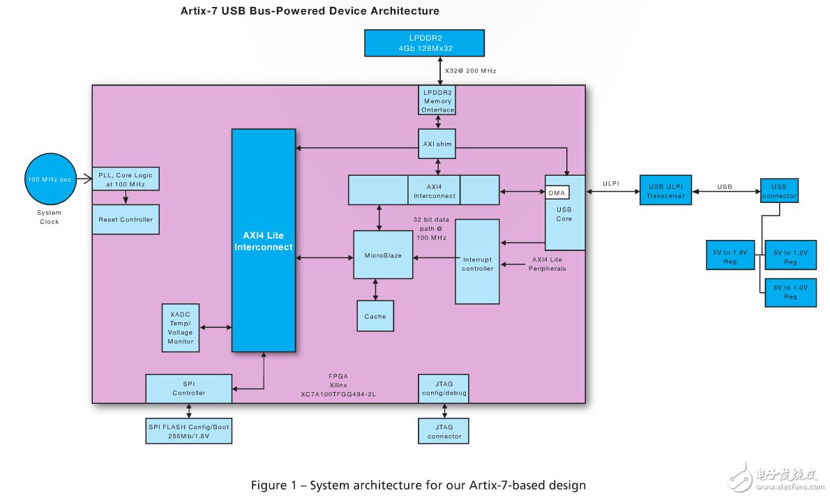
We identified several alternatives and built a complete system subsystem using MicroBlaze, a memory controller (using the Memory Interface Generator (MIG)), and an interface module for various peripherals using Vivado's IP Integrator tool. Estimated values ​​for precise power, size, and I/O. We quickly get synthesizable targets and use Vivado power reporting to calculate the power consumption.
Since the MIG itself does not provide an AXI local connection to the LPDDR2 device, we developed the link ourselves later. Before our AXI layer was completed, we used the MIG-generated LPDDR2 instance design for initial power estimation and size adjustment. Figure 1 shows the resulting system architecture.

Reducing the device's die temperature reduces leakage current consumption.
Strategies include minimizing device die size and choosing the largest possible package

As described in the Vivado DesignSuite User Guide: Xilinx Power Analysis and Optimization (UG907), lowering the device's die temperature reduces leakage current consumption. The strategy we use includes narrowing the device die size and choosing the largest possible device package based on the application's strict board space constraints.
We minimize conversion loss and regulator circuit cost by reducing the amount of power. After determining the device power requirements, we designed a voltage conversion circuit to reduce the rated USB 5V bus voltage to the rail voltage. So far, we have been paying attention to steady state current consumption. However, the inrush current consumption must also be considered. One way to minimize inrush current is to select a regulator with a soft-start function to control the power-up sequencing. You must balance the power-up sequence and ramp-time requirements of the FPGA with the USB requirements.
Easily respond to unexpected situations
Although various mechanisms are provided to properly shut down and remove USB devices, in reality many users will unplug the device in spite of warnings. If the firmware update process is not robust enough, problems can arise, resulting in unresponsive "brick" equipment, unpleasant customers, and costly equipment returning to the factory for firmware recovery. Anritsu stands out from the competition with the reliability and speed of high-volume manufacturing tests. Therefore, our main requirements include fast start-up time and fast firmware upgrade time.
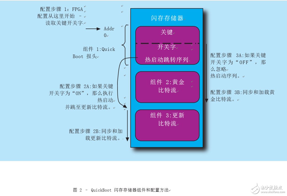
We solved this problem by implementing the QuickBoot Golden Mirror firmware upgrade architecture and process described in the Xilinx Application Guide XAPP1081 and summarized in Figure 2. The traditional 7-series read-back multi-boot solution uses a boot process that maintains a known "golden" image with a bitstream in the configuration flash memory. During the update process, the updated "work" image is loaded into memory after the "golden" image. If the update process fails or the "work" image is corrupted, the FPGA will automatically detect the error and read back to the "golden" image. The XAPP1081 Quick-Boot method further extends the process to provide a more complete configuration time and "golden" image update feature.
Building on the success of the project, we further look at how the next generation of Xilinx devices will enable more functionality for Anritsu products. For example, a large amount of power budget is occupied by off-chip SDRAM interconnects. We look forward to investigating how to use the updated 16nm UltraScale family of UltraRAM to reduce or eliminate this load, perhaps using the ARM7-enabled Zynq-7000 AllProgrammable SoC product line in the application.
For more information, please contact: During the update process, the updated "work" image is loaded into memory after the "golden" image. If the update process fails or the "work" image is corrupted, the FPGA will automatically detect the error and read back to the "golden" image. The XAPP1081 Quick-Boot method further extends the process to provide a more complete configuration time and "golden" image update feature.
Building on the success of the project, we further look at how the next generation of Xilinx devices will enable more functionality for Anritsu products. For example, a large amount of power budget is occupied by off-chip SDRAM interconnects. We look forward to investigating how to use the updated 16nm UltraScale family of UltraRAM to reduce or eliminate this load, perhaps using the ARM7-enabled Zynq-7000 AllProgrammable SoC product line in the application.
For more information, please contact the author: update, update the "work" Mirror loaded into memory after a "golden" image. If the update process fails or the "work" image is corrupted, the FPGA will automatically detect the error and read back to the "golden" image. The XAPP1081 Quick-Boot method further extends the process to provide a more complete configuration time and "golden" image update feature.
Building on the success of the project, we further look at how the next generation of Xilinx devices will enable more functionality for Anritsu products. For example, a large amount of power budget is occupied by off-chip SDRAM interconnects. We look forward to investigating how to use the updated 16nm UltraScale family of UltraRAM to reduce or eliminate this load, perhaps using the ARM7-enabled Zynq-7000 AllProgrammable SoC product line in the application.
China Phase Control Stud Thyristor,Stud Version Phase Control Thyristor supplier & manufacturer, offer low price, high quality Dc Power Encapsulation Thyristors,High Power Drives Thyristor Power Control, etc.
The output voltage of thyristor phase-controlled rectifier circuit can be regulated in a large range and has a small fluctuation, which has an impact on the electrical performance of ac power and devices.
Phase Control Stud Thyristor,Stud Version Phase Control Thyristor,Dc Power Encapsulation Thyristors,High Power Drives Thyristor Power Control
YANGZHOU POSITIONING TECH CO., LTD. , https://www.yzpst.com