Analysis of design and application of thermostatic automatic calorimeter based on S3C2410
introduction
This article refers to the address: http://
Performance characteristics of the calorimeter: 5.2-inch touch-type LCD screen with advanced technology from the United States, and an integrated installation method to ensure the firmness of the touch screen. Infrared technology, the material uses CRT display material to make the touch screen more durable. Multi-layer composite film covering, ensuring optimal color distortion, reflectivity and sharpness, sensitive sensitivity, high positioning accuracy, effective 90% wear resistance in the infested area, long life of up to 10 years, Chinese characters display, no external computer required . It can be operated directly and can be controlled by a computer. Chinese menu-style operation interface, simple structure, intuitive and easy to learn, easy to operate, stable and reliable performance, strong anti-interference ability for internal and external tube optoelectronic isolation. Using unique foam insulation technology, the experiment is not affected by external temperature.
Automatic water injection, no need to adjust the water temperature, just put the oxygen bomb into the barrel, the instrument can automatically complete all tests. The structure is reasonable, the production is excellent, the performance is reliable, and the failure rate is low.
The result is accurate, and the unique cooling correction system, water circulation system and software automatic, error compensation system have the functions of large water storage capacity and good thermal stability.
In recent years, with the continuous maturity of embedded technology, its cost has also been declining. The advantages of variable scale, flexible expansion, high real-time and stability, and small system kernel have gradually emerged.
1 Basic principles
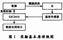
The thermostat calorimeter measures the calorific value by the oxygen bomb method. The heat of the substance placed in the oxygen bomb is burned and the heat released by the combustion is transmitted to the water and the instrument system through the cartridge, and the calorific value of the substance is calculated according to the change of the water temperature. The basic block diagram of its measurement is shown in Figure 1. According to the basic principle of oxygen bomb method measurement, the calorific value calculation formula is as follows:
Where: E is the heat capacity, unit: J/K; q1 is the ignition heat, unit: J; q2 is the total heat generated by the additive such as wrapping paper, unit: J; m is the mass of the sample, unit: g; Tc Temperature at the end of the main period, unit: °C; Tb temperature at the beginning of the main period, unit: °C, C is the cooling correction value, unit: °C.
It can be seen from the above formula that as long as the temperature of the water and related parameters are measured, the calorific value of the coal sample can be calculated.
2 system design
2.1 Hardware Design
The S3C2410 processor is a 32-bit microcontroller based on ARM's ARM920T processor core and 0.18um manufacturing process from Samsung. The processor has: independent 16KB instruction cache and 16KB data cache, MMU, TFT controller supporting TFT, NAND flash controller, 3 UART, 4 DMA, 4 Timer with PWM, I/O port, RTC , 8-channel 10-bit ADC, Touch Screen interface, IIC-BUS interface, IIS-BUS interface, 2 USB hosts, 1 USB device, SD host and MMC interface, 2 SPI. The S3C2410 processor can run at up to 203MHz.
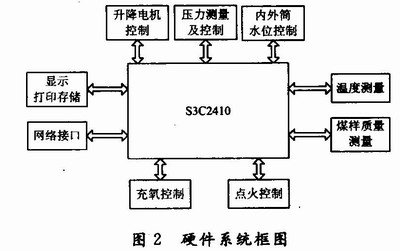
The connection diagram of the S3C2410 and the various parts of the calorimeter is shown in Figure 2. After the hardware is connected, it is necessary to software-drive each part to the port of the S3C2410.
2.1.1 ARM board selection
This design choice is more used in the market, while the S3C2410 processor is more typical in terms of structure and resources, mainly for the following reasons:
(1) High cost performance and the most widely used. As a classic ARM9 series processor, S3C2410 has the most complete data, and the development package of various drivers is the most, which is beneficial to developers.
(2) The design idea of ​​separating the core board and the bottom board allows the user to conveniently use the Core-Board for secondary development.
2.1.2 Sensor selection
Most of the current calorimeters use platinum resistance as the temperature measuring component; although it has the advantages of high precision, the maximum non-linearity error of the platinum resistance is up to 2% in the range of 0 to 800 °C without correction, and they belong to For analog sensors, the output signal requires analog-to-digital conversion, which not only complicates the circuit, increases the cost, but also increases the error.
Quartz crystal temperature sensor HTS-206 is one of them. It is produced by Japan EPSON company. Its oscillation frequency is around 40 kHz, and the operating temperature range is -55~+125°C. The measurement accuracy is corrected by multi-point difference method. The conditioning circuit of the O.05 °C quartz crystal resonator HTS-206 comprises three main parts: an oscillating circuit, a frequency divider and a counter. The conditioning circuit is shown in FIG.
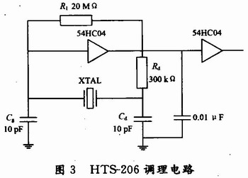
In the past, the method of measuring the frequency was to connect the FPGA chip to the chip. However, the operating frequency of the HTS-206 is about 40 kHz, which is in line with the performance of the S3C2410, in order to save costs. After the output of the HTS-206 is rectified and amplified, it passes the EQ0 port of the S3C2410 and uses the FIQ interrupt mode.
Use the software to set the gate time of the interrupt to Tw, and record the number of change cycles (or the number of pulses) N of the measured signal, then the frequency of the measured signal is:
2.1.3 Control section
The control part consists of oxygenation control, charge and discharge control, water level control, ignition control, and lifting motor control.
The oxygenation circuit mainly controls the flushing and releasing of the oxygen bomb. When the experiment starts, send a signal and open the valve. When the oxygen bomb is inflated to a certain pressure, it sends a signal to the S3C2410. The S3C2410 controls the valve to close when it receives a signal.
The charging and discharging water level control system mainly completes the water inlet, drainage and positioning tasks of the inner and outer cylinders. The water level of the inner and outer cylinders is measured by two detectors respectively, and the water level comparison is performed by the program, thereby achieving the purpose of quantifying the inner and outer cylinder water.
The ignition system controls the ignition device in the oxygen bomb. The specific control requirements are: the ignition of the ignition wire is performed after the self-test, and if everything is normal, the ignition is performed. If the ignition is successful, send a signal to the S3C2410 to start the temperature measurement system. If the ignition fails, exit this test.
2.1.4 Network Communication of S3C2410
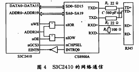
As shown in Figure 4, the S3C2410 uses the CS8900A-Q3 controller to extend the network interface module. Its transmission rate is 10 Mb/s. The CS8900 works in 16-bit mode, and the default working mode of the NIC chip reset is I/O connection. Since the interrupt levels of the CS8900A and S3C2410 are reversed, a NOT gate is required between the interrupt signal lines. The transmitting and receiving ends of the signal are connected to the CS8900A through the RJ45 interface, and then transmitted to the S3C2410, thus forming a hardware channel for Ethernet signal transmission.
2.2 Software Design
2.2.1 Establishment of the development environment
Before developing software for S3C2419, you need to establish a suitable development environment by following the steps below.
(1) Porting UBOOT to the S3C2410 development board.
(2) Using H-JATG software to read the information of the board CPU, and using the AXD Debugger software in the ADS development environment to establish the simulation development environment.
(3) Simulation establishes a minimum system, initializes each port, and sets parameters such as clock and power. After the simulation is successful, the initialized file is downloaded to the motherboard using ADS.
2.2.2 Programming the system
As shown in Fig. 5, according to the requirements of GB (T) 213-2003, the oxygenation time was set to 18 s. When the oxygenation pressure was greater than 3.2 MPa, the oxygenation pressure was too large, and the experiment was terminated. Omit the ignition and control part, the main procedures are as follows:
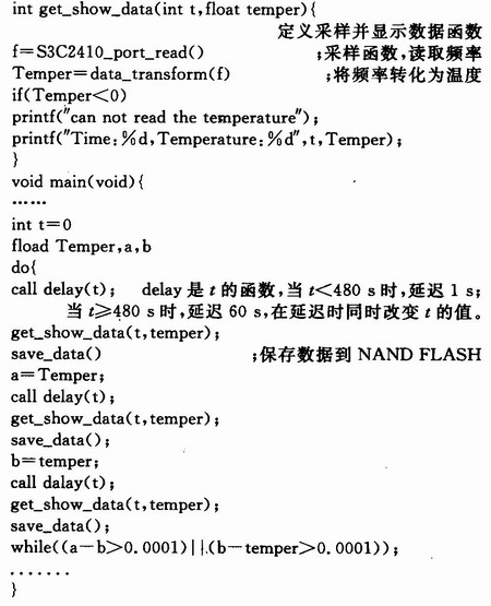
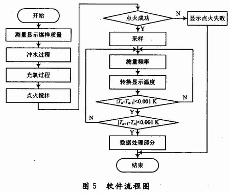
At the beginning of the experiment, samples are taken every second. After 8 min of experiment, samples were taken every 1 min. The experiment is over. Then enter the data processing section. This section includes the printing, storage of data and the transmission of data over the Internet. Due to space limitations, this part of the program is not listed.
3 Conclusion
Calorimeter is an important measurement instrument for energy production and energy consumption enterprises. Its measurement accuracy and efficiency directly affect economic benefits. In order to improve the measurement accuracy of the calorimeter, the temperature measurement accuracy, accuracy, stability and the like of the entire calorimeter system need to be improved and improved.
The design is strictly in accordance with the GB(T) 213-2003 standard, and is different from the data transmission mode of the conventional calorimeter using the 8-bit single-chip microcomputer, but the 32-bit data transmission mode using the S3C2410 chip. At the same time, it has high stability and can work normally in complex environments. Therefore, calorimeter is an important instrument for energy production and energy consumption enterprises, and its measurement accuracy and efficiency directly affect economic benefits. Calorimeter can be used to measure the calorific value of combustible materials such as solids and liquids in electric power, coal, coke, petroleum, chemical, cement, military, food, feed, wood, charcoal and scientific research industries. Due to its wide range of applications, calorimeters with higher measurement accuracy and efficiency have good development prospects and economic benefits.
All auto filters are designed to prevent harmful debris from entering any parts where air and fluid flows, including your engine, radiator, fuel lines and more. Once a filter is no longer performing its intended function, decreased performance-even engine damage-can result.
When your air filter is dirty, your engine is forced to work harder, resulting in poor fuel economy, higher emissions and, possibly, a loss of engine power. In turn, as a worst-case scenario, a clogged Cabin Air Filter can lead to under-performance of the A/C system, causing weak air flow from the cabin vents. It can also lead to unwanted, unfiltered air in the cabin. As for a mucked-up fuel filter, that`ll land you with a weakened fuel supply to injectors, a reduction in engine power, poor acceleration and lousy fuel economy-not to mention a potential breakdown.
They protect vital car parts by keeping harmful debris at bay so your car runs right. Filters also ensure your car runs more efficiently. The cleaner your filter, the more it allows for the maximum flow of air or fluid through the system. Like a clogged drain, a dirty filter starves the system of the vital air or fluid and makes each system it protects work harder to do its job. Once filters are dirtied, they should be replaced.
it`s recommended that you get your filters replaced every 12 months or 12,000 miles, but check your owner`s manual for specifics about your vehicle`s filter replacement schedules.
Automotive Filter,Car Air Filter,Car Cabin Air Filter, Car Oil Filter
Donguan Bronco Filter Co., Ltd , https://www.broncofilter-cn.com