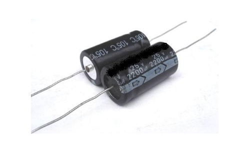
About polar capacitors and non-polar capacitors
A search for a saying on the Internet: "To connect two electrolytic capacitor anodes or cathodes in series to form a non-polar electrolytic capacitor." I don't understand this statement. Electrolytic capacitors generally have polar capacitors. If the anodes or cathodes of two electrolytic capacitors are connected in series to form a non-polar capacitor, then adding a voltage to the capacitor after the series connection will definitely have an electrolysis. The voltage across the capacitor and its polarity are opposite, so that it will not break down? I hope the heroes can help explain, thank you!
Non-polar electrolytic capacitors are easy to buy, our company is useful, of course, regular products from regular manufacturers.
Of course, the internals will not be "two electrolytic capacitors packaged in one case", but two layers of etched aluminum oxide foil.
- If you remove the electrolysis, you will find that the two layers of aluminum foil in the electrolysis are different: one layer is very thin and very smooth, the other layer is very thick and the surface is very rough, while the latter is actually Corroded, oxidized, and the insulating medium is the oxide film on it.
Since the two layers of aluminum foil are different in structure, they have polarity; as long as the two layers of aluminum foil are corroded and oxidized by aluminum foil, it is electrolessly electrolyzed.
As for: "It is correct to connect two electrolytic capacitor anodes or cathodes in series to form a non-polar electrolytic capacitor."
——Because the leakage current after the reverse connection of the capacitor is large because the reverse insulation resistance of the oxide film is small, the leakage current is large, and finally the electrolyte is heated and expanded or even boiled because of the large leakage current, and then the electrolyte evaporation fails, or Directly burst the shell and burst. When the two electrolytic capacitors are connected in series, it is as if the two diodes are connected in reverse. In any of the opposite directions, the partial voltage of the reverse resistance is small, and the voltage drop will mostly fall on the positive one. Above, so neither capacitor will overheat. The overall insulation resistance, of course, will be larger than a single resistor.

Of course, you must use two identical capacitors to reverse each other. It can't be too different, otherwise it will still be a rough problem!
For safety reasons, this method is only suitable for coupling low-voltage and low-energy applications. Do not do this under high voltage.
And its premise (principle) is that the forward resistance of the electrolytic capacitor is much larger than the reverse resistance, otherwise it can not be used.
This problem needs to be considered when the circuit is powered up and divided into transient and steady state.
Assume that the two electrolytic capacitors are positively connected to the positive electrode before the application of the alternating voltage, and the two electrolytic capacitors are connected in parallel with the diode, and the negative diode of the diode is positive (preferably draw it for analysis). The two capacitors are placed one left and one right, and there is no voltage on both capacitors.
Assuming that the polarity of the AC voltage is left and right and negative when power is on, the left diode is turned on to charge the right capacitor. The lower half cycle is left negative right positive, and the right capacitor discharge charges the left capacitor. This process continues until both voltages across the capacitor are equal to the AC peak.
Thereafter, both diodes are not conductive (AC voltage plus capacitor voltage up to zero) and have no effect in the circuit. Then the two capacitors are connected in series, and the total capacity is equal to half of the capacity of each capacitor.
Then remove the two diodes and consider xwj that "the forward resistance of the electrolytic capacitor is much larger than the reverse resistance", which is actually the same as a diode or diode in parallel with the capacitor and then a resistor in parallel. Except that the forward resistance of the capacitor causes a small amount of discharge of the capacitor, the rest are the same as the parallel diode. Because the positive and negative resistances make the capacitor charge faster than the discharge, the voltage across the two capacitors can remain close to the AC voltage peak during steady state.
The two negative electrodes of the electrolytic capacitor are connected to the negative pole and are identical.
Note that the two negative electrodes of the electrolytic capacitor are connected to the negative pole, and now there are four electrodes (two positive electrodes in the outer two negative electrodes), two layers of medium, and one wire. The two negative electrodes and a layer of medium and wires are removed, leaving two positive electrodes and one layer of medium, which is the configuration of the non-polar electrolytic capacitor.
I still can't understand the explanation of the maychang predecessor upstairs. You said "straight until the voltage across the two capacitors is equal to the peak of the AC", in this case, the voltage direction of the two capacitors is opposite, if the two capacitors are connected in series as a capacitor, then The total capacitance of this total capacitor is 0. If you do not consider the case of AC, only consider the case of DC, then use your "parallel diode" method to analyze, it seems that only one capacitor can be charged, that is, the total capacitance after series connection and the capacitor capacity that is connected the same.
"Only consider DC conditions"
Pure DC does not consider capacitance at all, as an open circuit. Need to consider the capacitor, it must be superimposed on the DC component.
You should use a signal with an AC component superimposed on the DC, and consider the circuit to reach a steady state based on the model of the parallel diode. To reach steady state, both diodes are not conducting and no current flows through the diode. Hint: At this point one of the two diodes is charged to the signal peak, which is the DC component plus the peak of the AC component. At this point the total capacity is still half of a single capacitor.
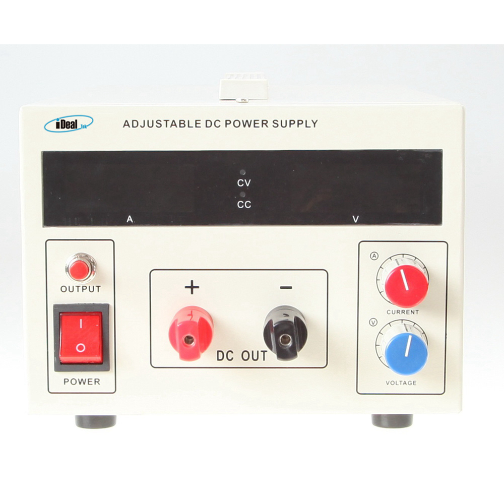
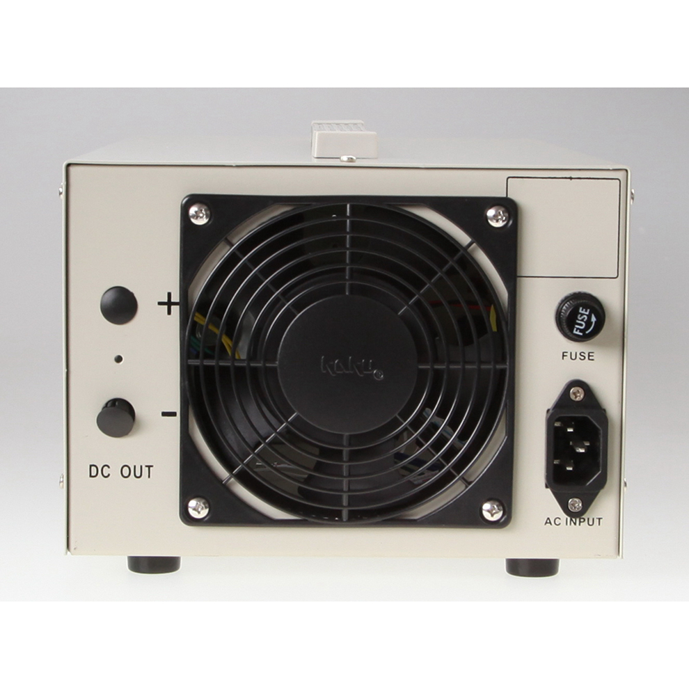
SMP series Bench DC Power Supplies are economical, MOSFETs-based, high switching speed, high power density desktop DC power supplies with output power covering 300W ~ 6KW, and maximum voltage up to 800VDC.
Compared with IGBT-based DC switching power supplies, MOSFET-based switching power supplies have a higher switching frequency, making this series Benchtop DC power supplies can use smaller semiconductor devices and LC filter units while ensuring low ripple, high precision, and fast response characteristics of the Benchtop Laboratory Power Supplies DC output. Which gives more space to use a smaller chassis size at the same output power, resulting the high-power density feature of this series Benchtop AC DC power supplies.


The main design purpose of this series of Bench AC-DC power supplies is to fulfill the needs of small laboratory test, precise experiment and universities.
At present, this series of Bench AC DC power supplies below 1KW adopts desktop chassis to match laboratory applications, they are mainly used in LED testing, small electroplating, heating of new materials, electrical component testing and other applications.
Bench DC Power Supplies, Desktop DC Power Supplies, Bench Laboratory Power Supplies, Benchtop AC DC Power Supplies, Bench AC-DC Supplies
Yangzhou IdealTek Electronics Co., Ltd. , https://www.idealtekpower.com