Using MAXQ2000 to achieve high-speed I² with MAX1169
Abstract: This application note provides the application circuit for the interface between the MAXQ2000 microcontroller (MAXQ20 core) and the MAX1169 16-bit ADC, and provides all the required firmware. The firmware routine is developed using Rowley CrossWorks IDE Version 1.0.
MAX1169 Overview The MAX1169 is a 16-bit low-power ADC with a 1.7MHz high-speed I²C-compatible serial interface. The MAX1169 supports fast mode (400kHz) and high-speed mode (up to 1.7MHz).
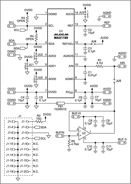
Hardware Description This application note uses the MAX1169 evaluation (EV) board and the MAXQ2000 evaluation board. The MAX1169 EV kit contains the MAX1169, all passive components required, and a proven PCB layout. The evaluation board circuit is shown in Figure 1. The MAX1169 evaluation board does not have a MAXQ2000 microcontroller; the system connects the MAXQ2000 evaluation board to the MAX1169 evaluation board through SCL, SDA, and GND. In addition, connect DVDD and AVDD to + 3.3V and + 5V power supplies, respectively.

Figure 1. Schematic of the MAX1169 evaluation board
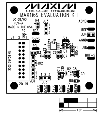
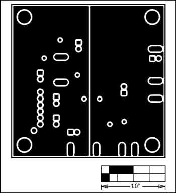
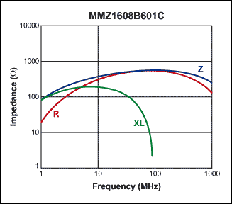
The pin arrangement of MAX1169 can easily realize the isolation of analog part and digital part. The analog parts of pin 8 to pin 13 on the right side of the IC share common ground, while the digital parts of pin 1 to pin 7 on the left side of the IC share common ground. Pin 14 is also a digital part, but can easily be shared with the part on the left side of the IC. Figure 2 shows an example of component placement. In order to achieve the best performance, it is recommended that designers use separate analog and digital grounds, as shown in Figure 3. Connect the two ground planes with magnetic beads near the MAX1169. A magnetic bead such as TDK's MMZ1608B601C is used to connect the two ground planes together to prevent the microcontroller's system clock and its harmonics from entering the analog ground. Knowing that the system clock of MAXQ2000 is 20MHz, MMZ1608B601C is selected according to its specified impedance and frequency characteristics. Figure 4 shows the relationship between the impedance of the MMZ1608B601C and the frequency.

Figure 2. MAX1169 EV kit component layout

Figure 3. The MAX1169 EV kit uses separate analog and digital grounds.

Figure 4. Correspondence between MMZ1608B601C magnetic bead impedance and frequency
The MAXQ2000 evaluation board contains complete software, hardware, code examples, and documents needed to get started with the MAXQ2000 microcontroller. The data sheet of the evaluation board also gives the circuit diagram of the MAXQ2000 evaluation board.
Firmware description The firmware routines are developed using Rowley CrossWorks IDE Version 1.0. The Maxim website provides Rowley Cross Works and third-party MAXQ® microcontroller development tools.
The CrossWorks main source file (main.c) initializes the MAXQ2000 UART, calls the high-speed I²C read function from hsi2c.asm, and sends the sample data of MAX1169 through the serial port. All serial port programs such as TeraTerm can be used to view examples on the PC.
The hsi2c.asm file is written in assembly and is a driver for high-speed I²C firmware. The assembler routine controls the high-speed I²C interface bit by bit through the MAXQ2000's general-purpose input / output (GPIO) port to obtain the sampling results from the MAX1169. The MAXQ2000's 20MHz system clock allows bit-controlled high-speed I2C interface rates up to 1.7MHz.
The hsi2c.asm file should be configured before the drive is enabled. Edit the I2C_ADDR definition state and change the I²C address of the device. For example, the encoding of the 0x7F address is: I2C_ADDR7 equ 0 I2C_ADDR6 equ 1 I2C_ADDR5 equ 1 I2C_ADDR4 equ 1 I2C_ADDR3 equ 1 I2C_ADDR2 equ 1 I2C_ADDR1 equ 1 Assuming that the system clock is the source code of 20MHz (MAXQ2000 crystal).
Download: Source code (ZIP, 10.5kB) Conclusion The specification of high-speed I²C was proposed as early as January 2000. However, few microcontrollers have so far included high-speed I²C peripherals. Because there are few devices, such as ADC, DAC, CODEC, and even the power supply voltage is specifically designed to support high-speed I²C interface. This application note presents a wider range of practical high-speed I²C routines.
MAX1169 Overview The MAX1169 is a 16-bit low-power ADC with a 1.7MHz high-speed I²C-compatible serial interface. The MAX1169 supports fast mode (400kHz) and high-speed mode (up to 1.7MHz).
Hardware Description This application note uses the MAX1169 evaluation (EV) board and the MAXQ2000 evaluation board. The MAX1169 EV kit contains the MAX1169, all passive components required, and a proven PCB layout. The evaluation board circuit is shown in Figure 1. The MAX1169 evaluation board does not have a MAXQ2000 microcontroller; the system connects the MAXQ2000 evaluation board to the MAX1169 evaluation board through SCL, SDA, and GND. In addition, connect DVDD and AVDD to + 3.3V and + 5V power supplies, respectively.

Figure 1. Schematic of the MAX1169 evaluation board
The pin arrangement of MAX1169 can easily realize the isolation of analog part and digital part. The analog parts of pin 8 to pin 13 on the right side of the IC share common ground, while the digital parts of pin 1 to pin 7 on the left side of the IC share common ground. Pin 14 is also a digital part, but can easily be shared with the part on the left side of the IC. Figure 2 shows an example of component placement. In order to achieve the best performance, it is recommended that designers use separate analog and digital grounds, as shown in Figure 3. Connect the two ground planes with magnetic beads near the MAX1169. A magnetic bead such as TDK's MMZ1608B601C is used to connect the two ground planes together to prevent the microcontroller's system clock and its harmonics from entering the analog ground. Knowing that the system clock of MAXQ2000 is 20MHz, MMZ1608B601C is selected according to its specified impedance and frequency characteristics. Figure 4 shows the relationship between the impedance of the MMZ1608B601C and the frequency.

Figure 2. MAX1169 EV kit component layout

Figure 3. The MAX1169 EV kit uses separate analog and digital grounds.

Figure 4. Correspondence between MMZ1608B601C magnetic bead impedance and frequency
The MAXQ2000 evaluation board contains complete software, hardware, code examples, and documents needed to get started with the MAXQ2000 microcontroller. The data sheet of the evaluation board also gives the circuit diagram of the MAXQ2000 evaluation board.
Firmware description The firmware routines are developed using Rowley CrossWorks IDE Version 1.0. The Maxim website provides Rowley Cross Works and third-party MAXQ® microcontroller development tools.
The CrossWorks main source file (main.c) initializes the MAXQ2000 UART, calls the high-speed I²C read function from hsi2c.asm, and sends the sample data of MAX1169 through the serial port. All serial port programs such as TeraTerm can be used to view examples on the PC.
The hsi2c.asm file is written in assembly and is a driver for high-speed I²C firmware. The assembler routine controls the high-speed I²C interface bit by bit through the MAXQ2000's general-purpose input / output (GPIO) port to obtain the sampling results from the MAX1169. The MAXQ2000's 20MHz system clock allows bit-controlled high-speed I2C interface rates up to 1.7MHz.
The hsi2c.asm file should be configured before the drive is enabled. Edit the I2C_ADDR definition state and change the I²C address of the device. For example, the encoding of the 0x7F address is: I2C_ADDR7 equ 0 I2C_ADDR6 equ 1 I2C_ADDR5 equ 1 I2C_ADDR4 equ 1 I2C_ADDR3 equ 1 I2C_ADDR2 equ 1 I2C_ADDR1 equ 1 Assuming that the system clock is the source code of 20MHz (MAXQ2000 crystal).
Download: Source code (ZIP, 10.5kB) Conclusion The specification of high-speed I²C was proposed as early as January 2000. However, few microcontrollers have so far included high-speed I²C peripherals. Because there are few devices, such as ADC, DAC, CODEC, and even the power supply voltage is specifically designed to support high-speed I²C interface. This application note presents a wider range of practical high-speed I²C routines.
Round Hole Pin Connector,Gold-Plated Round Hole Female Header,Dedicated Round Hole Pin Header,Single Row Round Hole Pin Connector
Shenzhen Jinyicheng Electronci Technology Co.,Ltd. , https://www.jycconnectors.com