Research on high-power LED lighting heat dissipation based on flat heat pipe
0 Preface
At present, lighting consumption accounts for about 20% of the total power consumption, greatly reducing lighting power is an important way to save energy. LED is a green light source in the 21st century. It has the advantages of energy saving, long life, environmental protection, small size, flexible control and fast response. It has broad application prospects [l]. However, the current LED luminous efficiency can only reach 10% to 20%, and the remaining 80% -90% of the energy is converted into thermal energy [2]. With the successful development of high-power chips, the application potential of LEDs in the field of lighting has been greatly improved, but at the same time, more heat has been released per unit area. The heat dissipation problem of high-power LED chips has become the application of current LED technology in lighting engineering. obstacle.
In order to ensure the normal operation of high-power LEDs, an effective heat dissipation design is required to ensure that the operating junction temperature of the LED is within the allowable temperature range. The stronger the heat dissipation, the lower the junction temperature. At present, the main heat dissipation methods used in road LED lighting fixtures are: natural convection heat dissipation, installation of fan or water cooling forced heat dissipation, heat pipe and loop heat pipe cooling.
Natural convection heat dissipation is dominated by conventional ribbed heat sinks, mainly by convective heat transfer of the surrounding air by means of fins. However, as the heat flux density of the chip increases, it is impossible to dissipate heat in a timely and effective manner by the gas convection method. Adding a fan to force the heat dissipation method has a high heat dissipation efficiency, but the system is complicated, the reliability is low, the maintenance and maintenance costs are high, and additional power consumption is required. The heat dissipation method of the loop heat pipe is costly, and the applicability remains to be further studied. Road lighting has a higher heat dissipation position. Due to the limited size of the body, efficient heat transfer by means of heat pipes becomes necessary. In addition, the existing heat sink emphasizes the heat conduction link and neglects the convection heat dissipation. Although many manufacturers have considered various measures to improve the heat conduction: such as using heat pipes and thermal grease, they do not realize that heat will eventually be Relying on the outer surface of the luminaire, the balance of heat transfer is neglected. If the temperature distribution of the fins is severely uneven, it will result in a greatly reduced efficiency of some of the fins (lower temperature portions). The existing heat sink for LED lighting is still limited to lower power LED lamps, and the effect is not obvious, the cost is high, and it is not easy to be applied to actual production.
It can be seen that the heat dissipation problem of high-power LEDs is an important scientific issue that needs to be further solved under the current energy-saving and emission reduction situation. In this paper, the flat heat pipe technology is applied to the heat dissipation of high-power LED lighting system, which makes full use of the advantages of good thermal stability of the flat heat pipe, strong heat transport capacity, and structural rules for installation and use. It provides theoretical basis for practical application through experimental research. .
1 Experimental device and test method
The test device is shown in Figure 1.
In this experiment, the voltage regulator converts the 220V AC voltage into the rated DC voltage of different LED devices, and delivers the current to the LED device. At the same time, the temperature is measured by the T-type thermocouple, and the Asilelt data acquisition system is used for data acquisition. And transmitted to the experimental computer in real time.
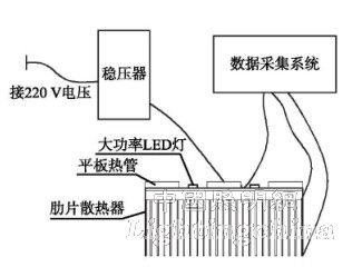
Figure 1 Experimental device circle
The flat heat pipe used in the experiment is made of metal aluminum, and the internal filling of R141b working fluid has the advantages of simple manufacturing process, good pressure bearing, compact structure and mature manufacturing process. In order to compare the actual effect of heat pipe technology on the heat dissipation of high-power LED lighting, in this experiment, an array light source consisting of 8 identical LED light sources with a power of 40W is matched with an external dimension of 350 mm × 122 mm × 38 mm. A ribbed heat sink with a height of 40 mm and a rib spacing of 10 mm is attached to the ribbed heat sink surface by a new flat heat pipe array [4], which is packaged into a new flat heat pipe fin heat sink and is naturally placed. The actual working conditions are compared with the traditional fin heat sink (the finned heat sink dimensions are the same as above).
In general, the junction temperature of high-power LED luminaires is controlled to within 70 °C. The junction temperature of the chip PN junction is directly related to the performance of the LED device. When the junction temperature rises, the luminous flux decreases and the luminous efficiency decreases (as shown in Figure 2 [3]), so the temperature of the lamp housing and the temperature of the external environment are used. It is worthwhile to judge the heat dissipation of Wensheng. The LED lighting heat sink used in this experiment is a new type of flat heat pipe experiment. The standard T-type thermocouple is placed on the bottom of the chip to measure the temperature of the chip. At the same time, the standard T-type thermocouple is used to test the measuring points on the heat sink (Figure 3). The temperature of the heat sink is obtained by the transient and steady-state heat transfer characteristics of the heat sink and the temperature of the LED junction temperature and the temperature of the different measuring points of the heat sink.
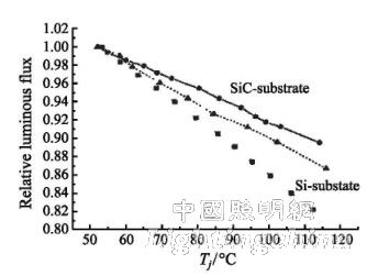
Figure 2 Relationship between white LED luminous flux and junction temperature
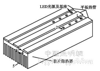
Figure 3 Distribution of each measuring point on the heat sink
In the experiment, the LED light source is placed in the same closed room to ensure the convection coefficient of the rib radiator and the air is the same, and the working time ensures that the lighting system achieves thermal balance. The placement of the ribbed heat sink should minimize the contact area with the surface of the test bench. The data collection point should be as far as possible from the position of the test bench; the flat heat pipe should be placed vertically so that the working state of the heat pipe is optimal.
2 Experimental results and analysis
As shown in Figure 4, when the heat sink is not heating the tube, the measuring point 1 indicates that the temperature of the chip is lower than 70 °C, which meets the heat dissipation requirements of the tested light source. The center temperature of the LED light source chip of the heating tube is about 5 ° C lower than the LED of the unheated tube in the allowable range of the junction temperature, and the temperature at the measuring point 2 of the surface position of the radiator is similar, and the heating tube at the end of the fin is lower than the tube without heat. The temperature of the end of the LED heat sink is 1 °C higher. The temperature drop of the LED heat sink surface of the heating tube is smaller, the temperature distribution is more balanced, and the rib portion tends to be gentle, and the temperature difference at each point of the surface of the heat pipe without heat pipe is greatly reduced. When the amount of heat dissipation is constant, the temperature of the chip in the heat sink of the heating tube is low. Correspondingly, the connection between the measuring points of the heating tube and the non-heating tube must have an intersection. It can be seen that when there is a heat pipe, the temperature drop at each point on the surface of the radiator is relatively gentle, the temperature of the ribs is better, and the utilization rate of the ribs is higher. However, the maximum temperature drop occurs at the chip and 2 points (near the pedestal). To further improve the performance of the LED heat sink, the pedestal will be a key consideration.
Figure 5 reflects the change in temperature of the fin rib end over time. After the heat pipe is added, the temperature of the surface of the heat sink reaches a stable time of about 0.85 h, which is obviously about 0.1 h faster than the time when the non-heated tube is stable. At the same time, the temperature of the end of the radiator fin of the heating tube is more affected by the environment. The fluctuation is large. After reaching a steady state, the temperature of the heat sink end of the heating tube is stabilized at approximately 41.6 ° C, which is approximately 1 ° C higher than the end temperature of the heat sink without heat pipe. The heat dissipation efficiency of the fin fin end is improved, and the function of the fin is well exerted, and the heat dissipation device of the heating tube saves heat dissipation under the same heat dissipation amount as compared with the ordinary fin heat sink without the heating tube. Volume, reduce weight. As shown in Figure 5, the temperature of the two heat dissipation cases overlaps within 0.5 h of the heat sink operation. This is because the end of the heat sink fin is far from the chip. When the temperature of the rib end is different from the ambient temperature at the beginning of the work. At lower times, it is easy for external influences to fluctuate.
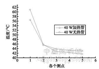
Figure 4 Temperature of each measuring point of the 40W LED heat sink
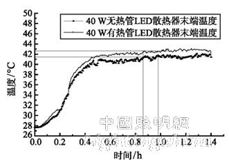
Figure 5 Temperature and time relationship of the fin rib end
3 Conclusion
The new flat-plate heat pipe is applied to the heat dissipation of high-power LED lighting. The heat dissipation condition of the heat-dissipating finned heat sink of the 40-watt LED array light source composed of 8 identical LED light sources is experimentally studied. D The center temperature of the light source chip is about 5 °C lower than the LED without heat pipe. The effect is quite obvious. After adding the heat pipe, the surface temperature stabilization time of the heat sink is about 0.85 h, which is obviously longer than the time when the heat pipe is not stable. Faster than 0.1h; for larger power LED array light sources, the LED lighting device of the flat heat pipe is added, the temperature drop at each point on the surface of the heat sink is relatively flat, the ribs are more uniform in temperature, and the ribs are more efficient. The heat dissipation performance is better, the various parts of the heat sink can work better, and the heat sink volume can be saved and the weight can be reduced.
Edit: Cedar
This battery is for replacing lead-acid battery, it has the standard appearance and size as well as capacity, but longer cycle life and high energy and good charge and discharge performance.
Capacity:100AH/150AH/180AH/200AH/250AH.
Voltage:12.8V, cycle life is more than 2000 times, also can customize the capacity.
Lead-Acid Battery,Lead-Acid Replacement Battery,Lifepo4 Lead Acid Replacement,lithium battey,12v lithium battery,24v lithium battery
Shenzhen Enershare Technology Co.,Ltd , https://www.enersharepower.com