Positive feedback to achieve hysteresis, what is the significance of the comparator circuit?
The comparator looks quite simple. They compare the two signal voltages and set the output high or low accordingly. However, if the two input signal voltages are very close, even a little noise on the input signal will cause the output to oscillate between high and low logic levels. Increasing hysteresis is the easiest way to solve this problem.
Hysteresis is when the system outputs it depending on its previous state. When the increase is delayed back into the comparator, the higher the high side switch threshold is set, the lower the low side switch threshold is set. Maybe you didn't notice that this is essentially the principle of working with an air conditioner thermostat. Let us take the time to think about it, if the thermostat is not hysteretic: when the minimum temperature fluctuates, the air conditioner may cycle the switch every few seconds, which will be noise, low energy efficiency, and burden the air conditioner. Increase the hysteresis back into the air conditioner thermostat to make the system work more efficiently.
Some comparators have built-in hysteresis, usually on the order of a few millivolts. This may be sufficient for some applications, but other situations may require increased external hysteresis. Increase the specific rise and fall thresholds required by the external hysteresis support system.
Hysteresis is achieved by positive feedback in the comparator circuit. This is one of the few examples where positive feedback works! Hysteresis does not have a threshold point, but creates different rise and fall thresholds. This keeps the output always low or high, not oscillating, even if the input signal is near the reference voltage. A comparator that adds hysteresis through positive feedback is also known as a Schmitt trigger.
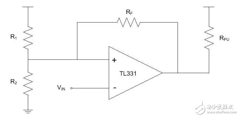
The example below shows the ON Semiconductor TL331 configured as an inverting Schmitt trigger. The L331 is a single-channel, low-power, open-collector comparator with no internal hysteresis. A resistor divider created by the R1 and R2 resistors sets the reference voltage on the non-inverting pin and the threshold voltage at the comparator output switch. Since this is an open collector comparator, connect a pull-up resistor to the output. The feedback resistor increases hysteresis by positive feedback. Typically, use a larger feedback resistor value of at least 100 KΩ.

Figure 1. Comparator configuration for inverting Schmitt trigger
For this inverting configuration, when the input signal is below the threshold, the output pin is high and the threshold voltage is pulled high by the feedback resistor. Thus, small voltage fluctuations on the input signal do not trigger the comparator output switch until the input voltage reaches a higher, adjusted, rising threshold. Once the input signal reaches the rising threshold, the output is pulled low. This pulls the threshold voltage through the feedback resistor to keep the output low until the input voltage drops below the lower regulation threshold voltage.
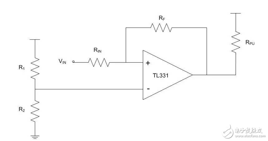
Non-inverting configurations work in a similar way to positive feedback. However, in this case, the threshold voltage set by the resistor divider does not change as the reverse phase configuration changes. Instead, the feedback regulates the input signal at the non-inverting node.

Figure 2. Comparator configuration as a non-inverting Schmitt trigger
In this configuration, when the input signal is low, the output is pulled low, causing the voltage of the non-inverting node to drop to a lower level. Once the input signal is high enough to pull the non-inverting node above the reference voltage, the output is pulled high, pulling the non-inverting node higher.
In the two circuits shown, adding hysteresis requires only one or two external resistors, and the resistance value can be adjusted to the threshold that best suits the particular application. When designed for comparators, increasing the hysteresis is a simple way to reduce the problems caused by noise on the input signal if the voltages on the input pins are likely to approach each other for a significant amount of time.
Membrane switch is an operating system that integrates key functions, indicating elements and instrument panels. It consists of four parts: panel, upper circuit, isolation layer and lower circuit.
When the membrane switch is pressed, the contacts of the upper circuit are deformed downward, and are in contact with the pole plate of the lower circuit.
After the finger is released, the contacts of the upper circuit bounce back, the circuit is disconnected, and the circuit triggers a signal. The membrane switch has strict structure, beautiful appearance and good sealing performance. It has the characteristics of moisture resistance and long service life.
Widely used in electronic communication, electronic measuring instruments, industrial control, medical equipment, automobile industry, smart toys, household appliances and other fields.
Membrane Switch, Poly Membrane Switch, Home Appliance Membrane Switch, Membrane Switch with Leds, Membrane Switch Model
KEDA MEMBRANE TECHNOLOGY CO., LTD , https://www.kedamembrane.com