Multi-switch detection interface: Designed for smaller, more efficient design integration
As the car's electronic controls, car body control modules (BCMs) can control a variety of functions related to car comfort, convenience and lighting, including door locks, windows, alarms, off sensors, interiors and exteriors. Lighting, wiper and turn signals. As shown in Figure 1, the BCM can monitor different drive switches and control power based on the corresponding in-vehicle load.
This article refers to the address: http://
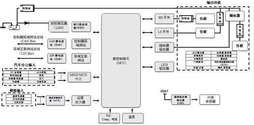
Figure 1: BCM block diagram
Typically, a BCM will include a microprocessor that handles the state of the car's 12V battery drive switch. Conventional passive components such as resistors and capacitors and diodes are used to connect signals to the microprocessor through interface circuits. You must carefully protect the microprocessor from battery voltage, electrostatic discharge (ESD), transients, and reversed batteries. In addition, you need to provide an agglomerated current to the bias switch input and ensure that the switch contacts are in good condition.
The actual case shown in Figure 2 illustrates how to handle an external ground switch input. Capacitor C2 shunts ESD and transient energy; diode D1 blocks high voltage; resistor R4 sets the agglomerated current at the switch; resistor R4 and R8 share voltage; resistor R1 through R3, transistors Q1 and Q2, capacitor C1, and general purpose input/output The (GPIO) pin enables or disables the agglomeration current.
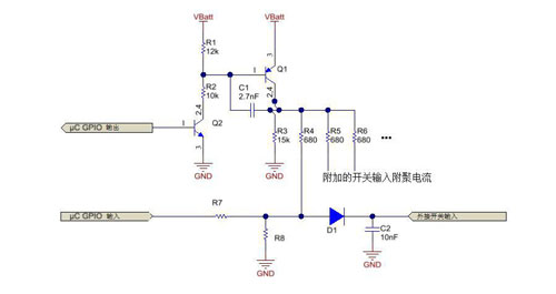
Figure 2: Separate agglomeration current structure diagram
The discrete method has three considerations:
• The microcontroller and microcontroller supply voltage must remain active for the agglomerated current to be active. This can seriously affect the minimum current consumed by the module in low power (disconnected) mode.
· This solution requires a large number of passive components such as transistors and resistors used to create agglomerated currents, as well as diodes, resistors and capacitors for each switch input. This leads to a larger size of the entire solution.
· The agglomeration current will vary with the battery voltage; for example, if the battery voltage drops by 30%, the agglomeration current will also drop by 30%.
The Multi-Switch Detection Interface (MSDI) is a device that can handle a variety of problems. It can aggregate the switch status information of the battery connection and the ground connection, and support the microprocessor through the serial peripheral interface (SPI).
Features that enable smaller size and higher space utilization solutions
The MSDI device integrates an adjustable agglomerating current that controls the current and sink currents of the external switch inputs for battery connections and ground connections. Since these currents are monitored by internal equipment monitoring, they are consistent with a wide range of battery input voltages. The MSDI switch input is also designed to handle load dump and reverse battery voltage, reducing the need for discrete blocking diodes and agglomerated current components, resulting in more board area and cost savings. As shown in Figure 2, the discrete 24-channel solution uses 75 resistors, 25 capacitors, 24 diodes, and 2 external transistors. In contrast, TI's TIC12400-Q1 Multi-Switch Detection Interface (MSDI) uses only 24 IO pin capacitors, 5 decoupling capacitors, a single resistor for interrupt output, and a single MSDI device.
Figure 3 is a one-to-one comparison of the discrete agglomeration current, reverse blocking, and ESD solution sizes for handling switch inputs and the automotive multi-switch detection interface reference design utilizing the TIC12400-Q1 device portion that includes all required external circuitry. size of. Currently, the total solution for a two-layer board with an MSDI reference design is 17.5mm x 18.8mm.
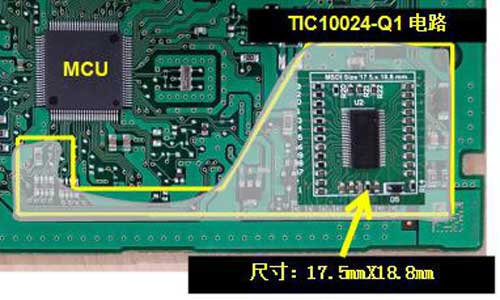
Figure 3: TIC12400-Q1 Solution Size
Achieve higher efficiency and lower power mode features
As mentioned above, to monitor the external switch in low power mode, the microprocessor needs to be powered and active. This means that the regulator of the microprocessor controller must also remain active at all times. This results in a higher quiescent current throughout the system in low power mode.
The MSDI device uses the car's battery directly, and it has an integrated low-power polling mode that allows it to monitor the user-selected switch contacts. For example, the TIC12400-Q1 has a low-power polling mode and a high-voltage open-drain interrupt output pin that allows the regulator to focus on changes in the switching state. This means you can turn off other circuits in the module for ultra-low-power sleep mode to meet the increasingly demanding requirements of original equipment manufacturers (OEMs) for sleep patterns.
Figure 4 shows an oscilloscope screenshot of the TIC12400-Q1 in low power polling mode. Channel 1 shows the voltage of the open switch contact and channel 2 shows the current consumption of the device.
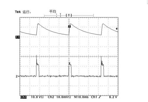
Figure 4: Low-power polling mode with switch monitoring
As you can see, the device can enable the agglomeration current, monitor the input voltage, and repeatedly return to low power mode while waiting for the switch contact to change state. Since all other circuits in the module are disabled, the average current of the module is lower.
As the capabilities of BCMs increase year by year, additional features such as built-in agglomeration currents, reverse blocking, and ESD protection for smart devices such as MSDI will help enable smaller switch contact monitoring solutions. In addition, due to the increasingly high current consumption requirements of the low-power mode, the TIC12400-Q1 with built-in low-power polling mode provides full system power savings of up to 98%.
Semi-Automatic Washing Machine Spin Motor
Semi-Automatic Washing Machine Spin Motor,Motor For Wash Machine,Al Wire Spin Motor,Semi Automatic Washing Machine Dryer Motor
WUJIANG JINLONG ELECTRIC APPLIANCE CO., LTD , https://www.jinlongmotor.com