Measurement of the influence of electrical equipment on grid power quality
Abstract: The measurement methods of harmonics, voltage fluctuations and flicker of electrical equipment and the main points of related technical standards are described in detail.
Keywords: standard harmonic voltage fluctuation flicker measurement
Measure of Effect of equipment
On Electricity Quality Provided by Network
Abstract:Measure of harmonic,voltage fluctuaTIon and flashing as well as those main technical standards are recounted in detail.
Keywords:Standard, Harmonic, Voltage fluctuaTIon, Measure
1 Introduction
The quality of power supply is a hot spot of concern. The large-scale adoption of switching power supplies and thyristor devices has improved the utilization efficiency of electric energy on the one hand, and formed a large amount of harmonic current in the power grid on the Other hand. Electronic products are subject to interference, and harmonic currents can also cause overload of the line current in the grid, affecting the power transmission capacity of the grid. In addition, the phase control of the AC power source also causes a change in the rms current value on the power grid, resulting in a significant fluctuation in the rms voltage value, which may cause the illumination device to flicker.
In order to ensure the quality of power supply and maintain human health, the International Electrotechnical Commission (IEC) TC77 committee has compiled two standards suitable for evaluating the impact of low-voltage equipment below 16A on grid power quality, namely:
(1) IEC61000-3-2 (1995) "Electromagnetic compatibility, Part 3: Limits, Chapter 2: Harmonic current transmission limits caused by low-voltage electrical equipment with rated currents of 16A or less."
(2) IEC61000-3-3 (1994) "Electromagnetic compatibility, Part 3: Limits, Chapter 3: In low-voltage power supply systems, the rated current is less than or equal to the voltage fluctuation and flicker limit of 16A equipment".
The IEC61000-3-2 standard has been equivalently converted into China's national standard, GB1765.1-1998 "harmonic current limit issued by low-voltage electrical and electronic equipment (device input current per phase ≤ 16A)", and has been officially published.
Internationally, the publication of the IEC61000-3-2 and IEC61000-3-3 standards is intended to replace the IEC555 series of standards published by the IEC in the early 1980s:
IEC555-1 (1982) "Interferences generated by household appliances and similar electrical equipment in power supply systems, Part 1: Definitions";
IEC 555-2 (1982) "Interferences generated by household appliances and similar electrical equipment in power supply systems, Part 2: Harmonics";
IEC 555-3 (1982) "Interferences generated by household appliances and similar electrical equipment in power supply systems, Part 3: Voltage fluctuations".
Comparing the names of the IEC61000-3 series and the IEC555 series of standards, it is not difficult to see that the new standard has expanded the scope of application of the standard, from the expansion of earlier household appliances and similar electrical equipment to all electrical equipment connected to the low-voltage power grid. major. Compliance with the new standards ensures that all equipment on the low-voltage grid is protected from harmonics and voltage fluctuations and protects the health of the electricity user.
In Europe, the European Community has simultaneously converted IEC61000-3-2 and IEC61000-3-3 into European standards at the same time as the publication of international standards. The standard numbers are EN61000-3-2 and EN61000-3-3. . The EC also provides for the enforcement of these two standards from July 1, 1998. This move shows that, like the enforcement of other electromagnetic compatibility standards, the impact of equipment on the quality of grid power supply will also become an important weight for international trade, and no one should take it lightly.
2 harmonic current test
According to IEC61000?3?2 and GB17625.1 standards.
2.1 Mathematical basis of harmonic measurement
According to mathematical analysis, any non-sinusoidal periodic waveform can be represented by Fourier series: ![]()
Where F0 is the DC component. If further set
![]()
Sinφn=an/Hn
Cosφn=bn/Hn
Then f(t) can be rewritten into ![]()
Therefore, the measurement of a non-sinusoidal periodic waveform can be converted to a measurement of its DC component (if there is a DC component) and the amplitude and phase angle of each harmonic.
2.2 Classification of equipment
According to the standard requirements, different types of electrical equipment can be classified into four categories, and different types of equipment have different harmonic current limits.
Class A refers to equipment with three-phase balance (the rated current of each line differs by no more than 20%), and other equipment that does not belong to the following three types of equipment.
Class B refers to portable tools (especially hand-held short-time working electrical tools), but for symmetrically controlled, short-time working household appliances (such as hair dryers, etc.) are still tested in Class A equipment.
Class C refers to lighting devices including dimming equipment. ![]()
![]() Class D refers to devices with a special waveform of input current (such as rectifiers and capacitors in the input circuit, so that the input current is within each half cycle, at least 95% of the duration is within the area of ​​the center), and the input The active power is less than or equal to 600W (for devices larger than 600W, it is still assessed according to the limits of Class A equipment).
Class D refers to devices with a special waveform of input current (such as rectifiers and capacitors in the input circuit, so that the input current is within each half cycle, at least 95% of the duration is within the area of ​​the center), and the input The active power is less than or equal to 600W (for devices larger than 600W, it is still assessed according to the limits of Class A equipment).
The harmonic current limits caused by Class A, Class C and Class D equipment are shown in Table 1, Table 2 and Table 3, respectively. For Class B equipment, the standard specifies 1.5 times that of Class A equipment.
Table 1 Class A equipment harmonic current limits
Table 2 Class C equipment harmonic current limits
Note: λ is the power factor of the circuit
For incandescent lighting, if phase control is used, the firing angle should not exceed 145°.
Table 3D Class Harmonic Current Limits
Note: The “mA/W†limit applies to devices with active power greater than 75W and may be reduced to 50W in the future.
2.3 Harmonic current measurement
Harmonic current measurement is divided into two types: steady state and transient state:
(1) Steady-state harmonic current measurement
If the relationship between the harmonic component and the fundamental wave has a periodic variation, the steady-state harmonic current can be measured. The limits mentioned in the GB17625.1-1998 standard are suitable for the steady-state harmonic current requirement.
(2) Transient harmonic current measurement
If the harmonic component does not change periodically with the fundamental wave, the measurement of the transient harmonic current is as follows:
â— If this situation is caused by equipment input or exit, and the duration is less than 10s, the harmonic current change of this transient process may not be considered.
â— If the maximum duration of each harmonic does not exceed 10% of the observation period limited to 2.5min, the limit of each harmonic current can be allowed to be relaxed to 1.5 times the standard specified steady-state limit.
2.4 test circuit
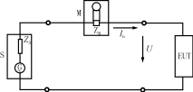
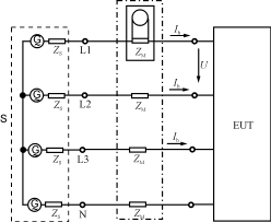
The lines in Figure 1 are suitable for testing single-phase and three-phase equipment, respectively.
There are different requirements for each part of the line.
(1) Test power supply S
The performance that the test power supply must have is:
â—The internal resistance should be small enough;
â— The output voltage should be adjustable within a certain range to meet the requirements of the power supply voltage rating in various countries and regions;
◠Voltage stability is ± 2%;
◠The frequency stability is within ±0.5% of the rated frequency;
◠For three-phase power supply, the phase accuracy of the phase-to-phase fundamental wave is 120 ° ± 1.5 °;
â—When the sample is running, the voltage harmonic content of the test power supply should be small (for example, the harmonic content of 3 times, 5 times, 7 times, 9 times and 11 times or more should be lower than 0.9% of the rated output voltage, 0.4%, 0.3). %, 0.2%, 0.1%; 2 to 10 times of even harmonic content should be lower than the output rating
Figure 1 harmonic current test circuit
(a) Test line for single-phase equipment (b) Test line for three-phase equipment
Note 1: S power supply, G ~ open circuit voltage of power supply, internal impedance of Zs power supply
M measuring device, Zm measuring device input impedance, EUT test equipment
U test voltage, h-th harmonic component of Ih line current.
Note 2: ◠The standard does not specify the values ​​of Zs and Zm, but the voltage drop caused by the input current flowing through Zm should not exceed 0.15V (peak);
â— The total error of the measuring equipment should not exceed 5% of the allowable value, or 0.2% of the rated current of the equipment under test, whichever is greater.
0.2% of the voltage).
(2) Test instrument M
For the measurement of harmonic current, various waveform analysis instruments such as frequency selective amplifier, heterodyne analyzer, multi-channel passive filter, spectrum analyzer can be used. Time domain analysis such as digital filter and discrete Fourier Transformer can also be used. instrument. However, from a worldwide perspective, in the harmonic current measuring instruments provided by major manufacturers, the time-domain measuring instrument of discrete Fourier transform is being considered as a reference measuring instrument.
2.5 Some provisions in the test
(1) For the lighting equipment with active power less than or equal to 25W, there is no requirement for harmonic current limit, and the test may not be carried out temporarily.
(2) Generally, the device does not allow the use of asymmetric power supply (refer to the positive or negative half-cycle current waveforms are different, or the number of positive and negative half cycles in each conduction time is not the same).
(3) For the direct power supply with half-wave rectification, the maximum power should be less than 100W, otherwise it will exceed the standard limit of the equipment.
(4) The equipment that directly uses the power supply half-wave rectification power supply can also have a short-time working portable device (such as a hair dryer) powered by a two-core cable.
(5) For heating elements, when the input power is ≤200W, or the operation does not exceed the limits of Class D equipment, the power supply may allow the symmetrical control method to control the power (as long as the positive and negative halves of the current waveform are the same; Or the number of positive and negative half cycles is equal in each conduction time).
(6) In the measurement, for harmonics greater than 19 times, if the spectral components decrease monotonically as the number of harmonics increases, the harmonics of 19 or more times may be excluded.
(7) In the measurement, if the harmonic current is less than 0.6% of the input current or less than 5 mA, the test will be passed as the same condition.
3 voltage fluctuation and flicker test
According to the ICE61000?3?3 standard.
3.1 Assessment content and limits
From the topic of this section, we must evaluate the two aspects, namely voltage fluctuations and flicker. The voltage fluctuation mainly reflects the sudden large voltage fluctuation on the power grid. Generally speaking, it has little effect on the flicker measurement, but the impact on other devices in the same power grid, especially electronic equipment, may be very large.
As a flicker measurement, the effect of continuous voltage fluctuations can be accurately assessed, which can reflect the unstable visual effects caused by temporally varying light stimuli to the human eye.
(1) Voltage fluctuations
There are three indicators for describing voltage fluctuations (see Figure 2).
Relative steady-state voltage change characteristic dc: refers to the percentage of two adjacent steady-state voltage differences and rated voltages separated by at least one voltage change, and the standard specification shall not exceed 3%.
Relative voltage change characteristic d(t): refers to a time function of the voltage effective value of each period with respect to the voltage change under steady state conditions where the voltage is at least 1 s. The standard stipulates that the relative steady-state voltage variation must not exceed 3% over a measurement period of more than 200 ms (or vice versa, if there is a relative steady-state voltage change greater than 3%, the duration must be less than 200 ms).
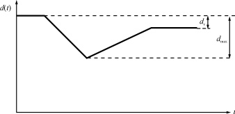
Figure 2 relative voltage variation characteristics
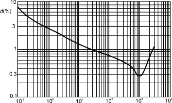
Voltage change per minute
Figure 3 Short-term flashing limit (Pst=1 curve)

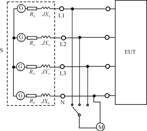
Figure 4 voltage fluctuation and flicker measurement line
(a) single phase (b) three phase
In the figure: EUT test equipment M measurement equipment
G power supply S is a power supply consisting of a voltage generator and an impedance Z
The reference impedance is at 50Hz:
Single-phase power supply RA=0.4Ω, JXA=0.25Ω
Three-phase power supply RA=0.24Ω, JXA=0.15Ω
RN = 0.16 Ω, JXN = 0.1 Ω
The maximum relative voltage variation characteristic dmax: refers to the difference between the maximum and minimum effective values ​​of the voltage variation characteristic and the percentage of the rated voltage, which shall not exceed 4%.
(2) flashing
There are two types of flashing: short-term flashing and long-term flashing:
â— Short-term flicker Pst: is the degree of flicker estimated in a short time (within 10 min), using Pst=1 as the threshold for flicker stimulation. Pst is actually the degree of flickering that the simulated person produces in a 50Hz incandescent lamp operating at 230V AC voltage in a 50Hz grid under voltage fluctuations, as shown in Figure 3.
Long-term flashing PLt: refers to the degree of flicker estimated over a long period of time (within 2 hours). The standard uses PLt=0.65 as the threshold for scintillation stimulation.
3.2 Measurement methods
Regarding voltage fluctuations and flicker, there are three alternative methods for evaluation methods mentioned in the standard, namely direct measurement, simulation, and analysis. The direct measurement method in which a scintillation measuring instrument is used is a reference measurement method.
3.3 measuring circuit
The measurement circuit of the direct measurement method is shown in Fig. 4.
(1) AC test power supply
The open circuit voltage of the test power supply shall be equal to the rated voltage of the equipment, and the voltage stability shall be within ±2%; the frequency stability shall be ±0.5% of the rated frequency (50 Hz), and the voltage harmonic distortion of the power supply shall be less than 3%. In addition, the maximum short-time flicker Pst of the test power supply itself is less than 0.4. It is also required to be verified before and after the test.
(2) Reference impedance
Since voltage fluctuations and flicker are determined by monitoring the voltage change at the load terminal, the appropriate line impedance must be selected as the uniform reference impedance during the test. The total impedance of the power supply line (including the internal impedance of the power supply and the reference impedance) should be appropriate to ensure an overall accuracy of ±8% over the entire evaluation measurement.
When the value of the power supply impedance is unknown, a reference impedance consisting of a resistor and an inductor must be added between the power supply and the device under test. The measurement should be performed at the power supply end of the reference impedance and the device end under test, and the measured from the power supply terminal. The relative voltage change maximum value dmax1 should be 20% smaller than the maximum value dmax2 measured at the device end.
(3) Measuring instruments and measurement accuracy
Although the standard lists a variety of methods for evaluating the voltage fluctuations and flicker of the equipment under test, the direct measurement method is the standard test method. The standard requirements for measuring instruments are: the measurement accuracy of the current amplitude should be within ±1%. If the real and imaginary parts of the current are not measured, but the phase angle is measured, the phase measurement error must not exceed ±2°, and the relative voltage change measurement accuracy is better than ±8%.
3.4 Some provisions in the test
(1) The limit test is only applicable to the power terminals of the device under test.
(2) For emergency switches and emergency interruptions, the limits do not apply.
(3) For equipment with a running time of more than 30 minutes, it is generally necessary to evaluate the PLt.
(4) When the voltage variation is caused by an artificial switching power supply, or the incidence rate is less than 1 hour per hour, Pst and Plt may be disregarded; the three indicators of voltage variation may also be relaxed to 1.33 times the limit value.
(5) In the evaluation of Pst and PLt, it is necessary to ensure that the most severe voltage change process is included in the working cycle of the sample.
(6) In the evaluation of Pst, the work cycle should be repeated continuously. If the operating cycle of the device is lower than the observation period and the sample is automatically shut down at the end of the run, the minimum time required to restart the device should be included in the observation period.
(7) In the evaluation of PLt, when the operating period of the equipment is less than 2h, and the test product does not work continuously in the usual time, the work cycle can no longer be repeated.
(8) When the device under test has multiple discrete control circuits, if each control circuit can work independently and does not perform switch control at the same time, then each circuit can be considered as a separate device for testing (or vice versa) If the control of these discrete circuits is performed simultaneously, then this combination is still tested as a single device).
(9) For the motor, the stalling method can be used to measure the maximum value dmax of the voltage variation occurring during the motor starting phase.
(10) For a three-phase balancing device, the voltage change of a relatively neutral line in the phase line can be measured. However, for three-phase unbalanced equipment, the voltage change of each relative neutral line should be tested.
(11) The test sample should be tested under the test conditions provided by the manufacturer. The motor should be pre-driven before the test to ensure that the results are corresponding to the normal use.
4 practical test system introduction
Instruments and test methods for harmonics, voltage fluctuations, and flicker measurements provided by major instrument suppliers in the world today are all based on standard test voltage sources and discrete Fourier transformers based on time domain analysis. The combination of instruments, except that some companies combine two functional parts in one instrument. Some companies use two independent instruments to form a system. When they are separated, they can be used in various fields. When combined, the test requirements of IEC61000-3-2 and IEC61000-3-3 can be completed.
Shanghai Sanji provides the latter test system consisting of a 6630 multifunction analyzer and a 6530 AC power generator.
In addition to the AC rms voltage, peak voltage, AC rms current, peak current, active power, power factor, waveform coefficient and frequency measurement of the traditional power analysis instrument, the 6630 multi-function analyzer is suitable for the diversification of power electronic products. And the requirements of the corresponding international standards, as well as voltage harmonics, current harmonics, voltage fluctuations, voltage flicker measurements, the results are automatically recorded and the waveform has an analysis function.
The 6530 programmable AC power generator is a high-performance, cost-effective power supply designed with advanced PWM technology. It provides pure AC power and is compatible with the 6630 multifunction analyzer for harmonic, voltage fluctuation and flicker measurements. .
In fact, in addition to the above, the 6530 programmable AC power supply can also be used as a multi-function AC power supply. For example, it provides an effective output voltage (0 to 300) V and a frequency of (15 to 2000) Hz. Therefore, in addition to satisfying the commercial requirements of (47 to 63) Hz, it is more suitable for naval and aeronautical applications requiring a frequency of 400 Hz or higher. The low frequency output can also be used for 20 Hz frequency testing of electric motors or air conditioner compressors. The output of the 6530 is a very pure sine or square wave (waveform distortion less than 0.5%).
In addition, because the 6530 programmable AC power supply uses digital frequency synthesis technology, the 6530 programmable AC power supply can also simulate various power supply interference, glitch, noise injection angle, voltage and frequency ramp up and down. This feature of the 6530 can meet the requirements of IEC61000-4-11 (1994) (equivalent to China's national standard GB/T17626.11-1998), for the electronic equipment against the power supply voltage transient drop, short-term interruption and voltage gradient resistance Disturbance test.
The above 6630 and 6530 instruments are equipped with RS-232 and IEEE488 interfaces, which can be combined with a computer to form a fully automated test system.
RM,High Quality RM,RM Details, Huzhou Kade Electronic & Technology Co., Ltd.
Low Frequency Transformer Co., Ltd. , http://www.chinaferritecore.com