How to prevent product failure caused by over-current stress in design
When a chip designer pulls a sensitive pin of an op amp out of the chip, it usually thinks whether the user will handle the pin carefully. Or just carelessly connect this pin directly to the AC? We all want to design a good product that can handle the extreme use of users. So, how to prevent product failure caused by electrical stress in the design?
The OPA320 is one of the most typical op amps. Its maximum rated parameter table is shown in Figure 1. It describes the maximum allowable supply voltage of the chip, the maximum allowable input voltage and current of the pin. According to the additional instructions in the parameter table, if the pin input current is limited, there is no need to limit the input voltage. The internal clamp diode allows an input current of ±10mA. However, limiting the input current requires a large input impedance when the input voltage exceeds a large number of normal values, which increases noise, reduces bandwidth, and may cause other errors.

The clamp diode begins to conduct when the input voltage exceeds the supply rail by approximately 0.6V. In general, many devices can withstand large currents, but as the voltage increases dramatically, the probability of device failure increases.
By adding an external diode, the device can greatly increase the ability to withstand large currents, while also increasing the degree of protection of the device. Commonly used transmission signal diodes on the market, such as the ubiquitous 1N4148, have a very low turn-on voltage drop (laboratory tests have shown that they are at least 100mV below the op amp's internal diode). After paralleling the internal diode of the op amp, most of the current will flow to the external diode when an input overcurrent is encountered.
Schottky diodes have lower turn-on voltages, which improves protection. But the shortcomings are also obvious, and its leakage current is too large. At room temperature, its reverse leakage current is usually microampere or greater and, at the same time, increases with increasing temperature.
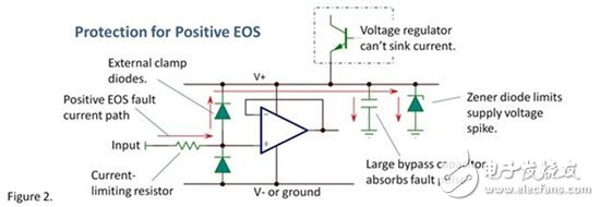
In addition, you need a power supply that is strong enough. Clamping diodes, whether internal or external to the op amp, require a relatively stable power source to dissipate energy. If the fault pulse is large, excessive current is injected into the power rail, and the power supply voltage is increased (or pulled down), then the pulse will subject the power supply terminal to excessive voltage stress, as shown in Figure 2. A typical linear power supply cannot sink current, so don't expect to use it as a power source. Large bypass capacitors can be used to sink large fault pulse currents. For continuous fault current, a Zener diode can be added to the input pin and power supply. The reverse breakdown voltage of the Zener diode is just above the maximum supply voltage of the system, so that the Zener diode is only turned on during the fault. For positive and negative power supply systems, the same protection circuit needs to be designed on both power rails.

Despite these measures, the pin input voltage may still exceed the value in the maximum rated parameter table, but the key issue is that the values ​​in the maximum rated parameter table are usually too conservative; chip damage is almost impossible at this voltage or current. . In general, the device is unlikely to be damaged (but not guaranteed) by significantly exceeding these parameters. It is easy to clamp to a voltage a few volts above the value in the maximum rated parameter table while achieving a lower failure rate. In many cases, the goal of the design is to reduce failure rates in the context of cost and performance tradeoffs.
There is no single solution that can handle all situations, and no protection circuit can meet all of the requirements at the same time. Protection circuit schemes vary widely in different applications. Different op amps have different sensitivities and the required level of protection varies widely. This may require you to have some creativity, it is best to be your own expert. Although doing some testing in extreme environments will cost some op amps, it is necessary.
Taillight Wire Harness apply in automotive,motocycle,bus,bike,truck.
Yacenter has experienced QC to check the products in each process, from developing samples to bulk, to make sure the best quality of goods. Timely communication with customers is so important during our cooperation.
If you can't find the exact product you need in the pictures,please don't go away.Just contact me freely or send your sample and drawing to us.We will reply you as soon as possible.
Tail Light Wiring Harness,Trailer Wiring Harness,Trailer Light Wiring Kit,Trailer Light Harness
Dongguan YAC Electric Co,. LTD. , https://www.yacentercns.com