How to Design a Universal Battery Charger
The first step in designing a battery charger is to choose a battery charger IC from the many solutions available. To make an informed decision, the design team must first clearly define the battery parameters (chemical composition, number of cells, etc.) and input parameters (solar, USB, etc.). The team then had to search for chargers that fit the input and output parameters, comparing numerous data sheets to determine the best solution.
The solution selection process should allow the team to select the best solution for the application, although of course revisiting the data sheet comparison should the design parameters change. What if this step could be skipped entirely? If designers could focus on the application solution, treating the battery charger IC as a black box and putting in the actual IC when it was really necessary to generate a viable solution, then How nice. At that point, regardless of the basic design parameters, the designer only needs to select a general-purpose battery charger IC from an off-the-shelf product. Even if application parameters change (input switching, battery type change, etc.), off-the-shelf battery charger ICs still work. No need to re-search additional datasheets.
We illustrate this by evaluating two very different battery chargers:
Design Team A is tasked with designing a battery charger that takes solar panel input and charges lead acid batteries. The charger must be self-contained (no microcontroller), but should be diverse enough to support several different solar panel models. They have a week to complete the schematic design.
Design Team B has a more complex charger project. Their design uses a 5 V USB power supply to charge one Li-Ion battery at 1.3A with a 4.1 V terminal voltage per cell. They expect the charge voltage to drop to 4 V and 0.5 A per cell above 47°C, and stop charging above 72°C. The microcontroller in the system needs to know the voltage, current, temperature and health of the battery. They also only had one week to complete the schematic design.
It turns out that both design teams can use the same battery charger IC, and the device is arguably the best choice for both applications.
good product, small size
The LTC4162 35 V/3.2 A monolithic step-down charger is simple in design and versatile. The LTC4162 can work either standalone or in conjunction with a host controller, providing solutions from basic to complex. A full-featured I2C telemetry system allows the user to selectively monitor the battery and implement custom charging parameters based on battery model. A true Maximum Power Point Tracking (MPPT) algorithm allows the charger to operate optimally against any high impedance source such as a solar panel. The charging algorithm is tailored to the chosen battery chemistry: Lithium Ion, LiFePO4 or Lead Acid.
These functions are packaged in a 4mm × 5mm QFN package, with typical solutions measuring approximately 1cm × 2cm.
Feel the power!
Never underestimate it because of its small size. The LTC4162 can support more than 60 W of charging power even using only the integrated switching FET. The LTC4162 utilizes internal thermal self-monitoring of chip temperature to regulate charge current so that overheating never occurs, even in the hottest environments or in the smallest enclosures.
PowerPathâ„¢ FETs (INFET and BATFET) ensure that the system load (VOUT) is always powered by VIN when the input voltage (VIN) is present, and from the battery if there is no VIN. Using an external N-channel FET enables a low loss path without limiting the amount of current that can be delivered to the load.
Figure 1. What kind of charger is suitable? These are two very different battery charging systems: can they use the same charger IC?
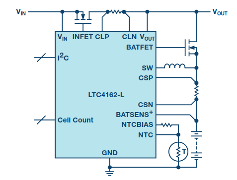
Figure 2. The application circuit of the LTC4162 is as simple as a fully functional switching battery charger.
Telemetry and Control
While the LTC4162 can operate without a host controller, many aspects of charging can still be monitored and controlled via the I2C port. An on-chip telemetry system reads system and battery voltage and current in real time. Various limits and alarms can be set to notify the host controller when a measurement meets a configurable threshold or enters a specific state of charge. For example, a common design function is to enter a power mode when the battery voltage drops to some lower limit. But instead of the microcontroller constantly polling the battery voltage, the LTC4162 can monitor it and notify the host controller when this limit is reached. At this point, the host can turn off the main load and enter a low-power state.
Figure 3. The LTC4162's integrated telemetry system can meet virtually any monitoring and alerting requirement.
The telemetry system can also measure battery series resistance (BSR) as an indicator of battery health. BSR measurements can be set to run automatically, and alarms can be configured to notify the host controller when the BSR exceeds a custom upper limit, at which point the host can signal the user that the battery needs to be replaced.
When input power is not available and the system is powered by battery, the LTC4162 automatically shuts down the telemetry system to preserve battery life. If measurements are still required, the telemetry system can be forced through I2C commands, at which point it enters a slower low-power telemetry mode that takes measurements every 5 seconds. The telemetry rate can be set to a high speed 11ms/read rate at any time if desired.
It's getting hotter in here
The LTC4162 implements a temperature-regulated, customizable charger. For Li-based chemistries (Li-Ion and LiFePO4), the LTC4162 can be charged with JEITA temperature control. The JEITA specification allows the user to set a custom temperature range in which to charge the battery with a custom battery charging voltage and current. This also allows the designer to determine the high and low temperature at which the battery should stop charging. The default JEITA settings are suitable for a wide variety of batteries without host processor intervention, and this feature enables the LTC4162 to meet the temperature profile requirements of any battery.
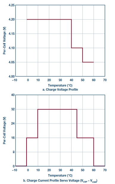
Figure 4. Default Li-ion battery JEITA curve.
Similarly, for lead-acid batteries, the temperature compensation algorithm linearly reduces the target voltage for each charging stage as the temperature increases. These voltages can be set for offset via I2C commands, and the compensation slope can be modified simply by changing the thermistor.
MPPT and input conditioning
For simplicity, many solar panel voltage regulator circuits set the maximum power point voltage to a constant value. In reality, VMPP drifts with illumination, and partially shaded solar panels may have multiple power peaks. By scanning the entire voltage range of the panel connected to its input power supply, the LTC4162's advanced maximum power point tracking (MPPT) algorithm takes all variables into account and is always set at the maximum power point. In addition to occasionally scanning the range of the solar panel, the LTC4162 also dithers the input regulation voltage to continually spot small changes in VMPP. These functions do not require custom programming, so panels can be switched without modifying the charger.
The benefits of input regulation also extend beyond solar panel power. For example, many USB cables have a lot of series impedance, which causes the voltage at the charger's input to drop when current is drawn. The undervoltage current limit feature of the LTC4162 regulates this current to maintain a minimum voltage at the input.
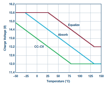
Figure 5. Default 12 V lead-acid battery temperature profile.
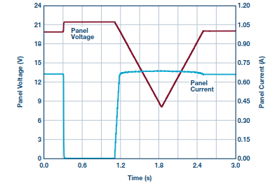
Figure 6. Global scan of a solar panel.
USB power delivery
The LTC4162 is also compliant with the USB Power Delivery specification and can deliver up to 100 W of power over a USB Type C cable. The input current limit of the LTC4162 is configurable to prevent overloading the input adapter. When the input current reaches the limit, the system load can still draw the required power from the input, but the battery charging current is reduced so that the input current limit is not exceeded. For USB PD, this means that one LTC4162 circuit can be powered by various power adapter configurations.
low power transport mode
When products need to be shipped or stored for extended periods of time, I2C commands can put the LTC4162 into a low-power state, reducing current consumption on the battery to about 3.5 µA. During this time, the circuit can optionally be configured to remove power from the system load.
IC version
To simplify design and documentation, the LTC4162 is available in different versions based on battery chemistry, charging parameters, and whether MPPT is enabled by default. Table 1 lists all optional versions of the LTC4162.
Table 1. 18 IC versions provide users with the most suitable device for any application
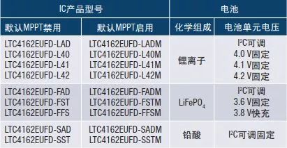
Each version is pin compatible and can be interchanged with another during prototyping. Interchangeable versions of the LTC4162 allow products with different battery chemistries, charging voltages or input power to use the same circuit, simplifying product creation.
To simplify documentation, the LTC4162 data sheet is divided into different versions based on different chemical compositions. Li-ion, LiFePO4 and lead-acid batteries each have separate data sheets.
in conclusion
Design team members used to spend all day reading data sheets for various battery chargers, power monitors, and solar regulators, and hours writing code for custom temperature-regulated charging algorithms and manually wheeling polling measurements to detect when limits are exceeded, they may now just consider having a universal battery charger. The LTC4162 would be the best choice.
The Vinyl Examination Gloves are single use only, disposable gloves intended for medical purposes to be worn on the hands or fingers of examiners. The gloves are powder-free, clear and are made of poly vinyl chloride. The gloves are offered non-sterile and are available in small, medium, large and extra-large sizes.
A patient examination glove is a disposable device intended for medical purposes that is worn upon the examiner`s hands or fingers to prevent contamination between patients and examiners.
Normal Packaging Specifications: 100PCS/BOX, 10BOX/CTN.
pvc glove, pvc hand gloves, pvc coated gloves, pvc gloves price, vinyl gloves
Jiangmen soundrace electronics and technology co.,ltd. , https://www.soundracegroup.com