High speed G. 729ab vocoder design and its application in media gateway
In VoIP media gateway devices, voice compression coding is one of its key technologies. In the ITU-T voice compression codec standard for VoIP, G. 729 is a widely used one. G. The 729 uses the "Conjugate Structure Algebraic Code Excited Linear Predictive Coding" (CS-ACELP) algorithm. The algorithm has a frame length of 10 ms and a coding rate of 8 Kb/s. G. 729 has two attachments: Annex A gives a low-complexity algorithm for multimedia synchronization of speech and data; Annex B adds a silence detection compression algorithm based on the standard algorithm to reduce the average transmission rate, including silence detection. (VAD) and comfort noise generation (CNG). Literature on G. The specific principles of the 729 speech compression coding algorithm are described in detail. The discussion in this paper focuses on the language optimization of the algorithm, the DSP hardware interface design of the vocoder, and its application in the media gateway.
1 G. 729ab codec core algorithm optimization This article selects TI's TMS320C6203 chip as the core to achieve G. 729ab vocoder design. Code Composer Studio (CCS), the integrated development environment of TMS320C62xx series DSP, supports standard C language and assembly mixed programming. In order to improve the efficiency of codec algorithm, this paper is the standard G of ITU_T. 729ab's C language source code is optimized for assembly instructions. At the same time, the upper codec control function is developed in C language to improve the maintainability of the vocoder.
The C62xx adopts a 6-stage pipeline structure and provides A and B groups (32 total) general registers and 8 functional units (.L1, .L2, .S1, .S2, .M1, .M2, .D1 and .D2). At the same time, there can be up to 8 instructions in parallel at different execution stages. The pipeline structure is an important technology for DSP to achieve high-speed operation. Since the instruction cycles of different instructions are different, it is necessary to insert enough NOP (null operation) instructions after the multi-cycle instruction to avoid pipeline conflicts.
At G. There are a large number of loop bodies in the standard C code of 729ab. The key jump instruction B of the loop control needs to wait for 5 instruction cycles. A large number of NOP operations will reduce the efficiency of the code. In order to improve the efficiency of the loop, the order of the instructions can be arranged reasonably, and the pipeline operations of the operations of the multiple C loops can be completed in one assembly loop. Take the assembly instruction to implement the following simple for loop to find the signal energy of the program segment as an example: 
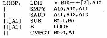
The above example can be implemented using the following assembly block: 
After optimization as above, the loop body LOOP is only one cycle, in which there are six instructions running in parallel. Among them, the memory read instruction LDFI takes 4 cycles, so the multiplication instruction SMPY multiplies the memory read result which is traced back four cycles. Similarly, the SMPY instruction takes 2 cycles, so the SADD instruction adds the multiplication results before 2 cycles. B0 and A1 are used together for loop control. In the five delay periods waiting for the jump command B to be valid, the subsequent counts of the subsequent loop are sequentially performed, the multiplication of the previous third loop, and the summation of the previous loop. , loop control and jump instructions, and so on. The above optimization achieves optimal cycle efficiency.
After the design is optimized, the core codec algorithm code is fully compliant with ITUT G. The 729ab standard and passed all test vectors of ITU-T. The vocoder is implemented using the TMS320C6203 with a frequency of 300 MHz. The single chip can support 31 channels of G. 729ab algorithm.
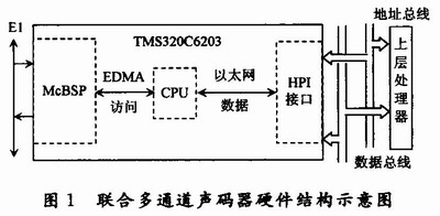
2 The DSP hardware interface of the vocoder is designed in the media gateway. The function of the vocoder is to realize the codec conversion between the E1 voice signal of the PSTN and the packet voice compression signal of the data network. The TMS320C6203 on-chip curing McBSP interface (multi-channel cache serial interface) and HPI interface (main processor interface) can realize the connection between DSP and E1 bus, and data network layer processor. The structure diagram is shown in Figure 1.
This article refers to the address: http://

The TM320C6203 works with the EDMA (Enhanced Directory Memory Access) controller through the built-in McBSP to implement links to the E1 standard interface. Set the receiving/transmitting control register (R/XCR) of McBSP to enable the serial port to send and receive data according to the standard E1 data format; set the serial port pin control register (PCR), control the serial port to use the clock and frame synchronization signal of the external E1 bus; set the serial port The control register (SPCR) controls the R/XINT (receive/transmit interrupt) of the serial port to be responded by EDMA.
The TMS320C6203 supports 16 EDMA channels, and its 12 to 15 channels can be used to respond to serial port reception and transmission interrupts. Take the serial port receiving data as an example: In this design, two serial data receiving buffer areas of ping and pong are designed.
The data in the serial port register is buffered to the ping buffer area through the EDMA mode. When the ping buffer area is full, the EDMA parameter is overloaded, the control is switched, the data is buffered to the pong buffer area, and an EDMA interrupt is given, and the CPU is notified to read one frame of data. . The process of sending data through the McBSP interface is completely similar.
The vocoder is connected to the upper layer processor through the HPI interface of the DSP to realize the transmission and reception of the packet voice compression signal of the data network. In the HPI interface, the Ethernet data transmission/reception buffer area is designed, and RP (Read Pointer) and WP (Write Pointer) are designed for each buffer area to control the upper layer processor and DSP. Interacting between encoded data. At the same time, the upper processor sends an instruction to the vocoder through the HPI interface to control the opening or closing of the channel.
3 Application Design in Media Gateway The main control program inside the vocoder uses the timed interrupt mode to access the HPI interface, and opens or closes the channel according to the instructions of the upper processor. At the same time, the main program uses the polling method to process the PCM voice signal from the E1 interface; the codec algorithm parameters are set according to the corresponding channel working state, and the voice signal is compression-coded; the encoded voice data is output to the upper processor through the HPI interface. Enter the digital network. The encoded data from the digital network is reverse processed using a completely similar polling process.
Since digital networks are packet communications, there must be a suitable multimedia real-time streaming network transmission protocol to ensure speech continuity. In the HPI interface control program of the vocoder, an RTP (Real-time Transport Protocol) interface is provided for the upper processor to complete the output and input of the encoded and decoded data packets and the corresponding RTP. The framing and deframing functions are designed as follows:
RTP packing and sending: RTP packets consist of a header and a data part with a fixed format. The encoded voice data is organized into an RTP header and an RTP payload according to the requirements of the RTP packing parameters. The key fields in the RTP header are SN (Sequence Number) and TS (Time Stamp). The SN is used to sort the RTP packets. The SN is incremented by one each time an RTP packet is sent. The TS is used to identify the time when the first byte of the RTP packet is sampled, and is incremented by the voice sample; for the voice packet and the silent compression packet, the TS value is consistent. In addition, the PT (Payload Type) field in the RTP header is used to indicate the data encoding format of the RTP payload. The standard audio payload type is specified in RFC3550: G. The PT corresponding to the 729 code is 18.
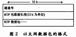
Since there is no length field in the RTP header, the RTP packet is externally extended: the RTP packet is used as a payload, and the RTP packet data length and channel number are added to form an "Ethernet packet". For the 32-bit addressing HPI bus interface of the C6203, the Ethernet packet format is designed as shown in Figure 2.

RTP packet transmission: write "Ethernet packet" to "Ethernet data transmission buffer". First, the remaining space is determined according to the read/write pointer of the buffer area; if the write space is insufficient, the write operation is discarded, and the data packet is discarded at the same time. If there is enough write space, the packet is written to the transmit buffer and the write pointer is updated. The upper layer processor determines whether there is new data in the buffer area according to the read/write pointer of the buffer area, performs a read operation, and updates the read pointer.
RTP packet reception, sorting, and caching: Packet communication needs to consider the anti-shake processing of speech. This article implements debounce by setting a static jitter buffer. First, according to the read/write pointer of the "Ethernet data receiving buffer area", it is judged whether a new data packet arrives, and if so, the data packet is arranged in the RTP buffer queue of the corresponding channel according to the SN and TS of the RTP. Repeat the above process until all the packets in the "Ethernet Data Receive Buffer" have been read, and then update the DSP read pointer of the buffer. For each channel's RTP buffer queue, when the buffered voice data reaches a predefined threshold K, a flag is given to allow the channel to begin speech data decoding. If the data packet has a jitter delay, the decoded speech can continue to keep the K time unit uninterrupted.
4 Conclusion Based on pure assembly parallel optimization, an efficient G. 729ab vocoder; using the TMS320C6203 on-chip peripheral McBSP to implement the standard E1 interface to connect to PSTN; designed the RTP protocol interface for packet data transmission and reception, using the HPI interface of TMS320C6203 to connect with the upper processor to make the vocoder Flexible for media gateways.
Lithium Battery,Lithium Batteries,Lithium Polymer Battery,Lithium Iron Phosphate Battery
Power X (Qingdao) Energy Technology Co., Ltd. , https://www.qdpowerxsolar.com