Discussion on the application of finite impulse response filter in sound reinforcement system
Recently, finite impulse response (FIR) filters have been popular in foreign countries. Like other things in the audio world, finite impulse response (FIR) filters have been around for a long time since their inception, and they continue to innovate in practical applications. We have been waiting for "filtering the savior" to make it a "magic bullet" for sound reproduction?
The answer is obviously no. But finite impulse response (FIR) filters can also change the game rules of some applications. First, let's examine the application of FIR filters in sound reinforcement systems, including some basic signal principles and processing time and frequency domain signals with modern audio and acoustic analyzers.
FIR filter
One way to understand the FIR filter is to understand its competitor, the Infinite Impulse Response (IIR) filter . In general, IIR is an analog or analog digital filter . The IIR responds by feeding back the output signal to the input and performing signal processing. This "recursive" behavior theoretically means that the impulse response of the filter never decays to zero. In practical applications, only the output signal is finally reduced to the noise floor. If not properly designed, the IIR filter is unstable. All analog filters are infinite impulse response.
For example, we use an analog or IIR parametric equalizer to create a speaker equalization curve (Figure 1, Figure 2), a high-pass response and a low-pass response, and the gain and attenuation of the filter in the passband.
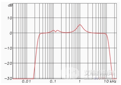
Figure 1: Equalizer frequency amplitude response
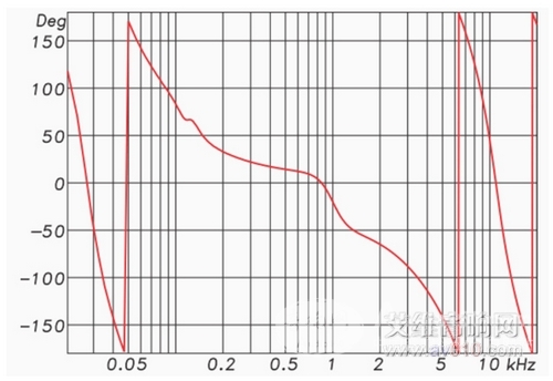
Figure 2: Equalizer frequency phase response
Each bump in the response represents the phase offset of the frequency (negative phase angle), and each pit represents a phase offset (forward phase angle) of opposite frequency. As the frequency increases, both high-pass and low-pass responses produce a negative phase angle. In other words, the change in amplitude response is accompanied by a shift in phase response. These phase shifts are unavoidable and are inherent to the filter . In fact, one can usually guess the phase response by looking at the amplitude response map. This predictable relationship between amplitude and phase is called the "minimum phase", which is an ideal property of the filter .
This is because the bumps and pits of the speaker frequency response in the speaker usually represent the minimum phase. This means that the equalizer completely "equalizes" the response of the speaker, producing a smoother amplitude and phase response. But "minimum phase" does not mean there is no phase offset. "Minimum phase" refers to the lowest possible displacement in a given amplitude response and is predictable and can be calculated by a measurement procedure.
Linear phase
The FIR filter varies in its amplitude response and does not produce a phase response offset. In the case where Fig. 1 is unchanged, the phase shift generated by it is as shown in Fig. 3. The amplitude and phase responses for the minimum phase filter are interdependent, while for FIR filters they are independent of each other. The FIR filter can change the amplitude without changing the phase. 
Figure 3: Linear phase
The real highlight of FIR is in crossover applications. The high-pass filter (HPF) is used to protect the speaker drive and can be used with the “steep slope†of the FIR, which can reach 96 dB/eight-order. If it is a "steep phase" filter (IIS or analog), a "steep slope" will produce a terrible phase shift. Still take Figure 2 as an example. The "time smear" caused by the filter directly limits the steepness in the IIS crossover network. Figures 4 and 5 show the 48 dB/octave Linkwitz-Riley IIR in a crossover network. 
Figure 4 
Figure 5
Figure 6 shows the amplitude response of the 8th order FIR in the crossover network. The slope of the filter is steeper than IIS. Figure 7 shows the group delay (GD) response of the filter, and Figure 8 shows the phase response of the excess group delay. 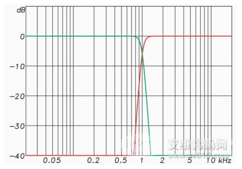
Figure 6 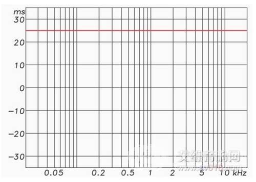
Figure 7
The FIR crossover network allows both the fish and the bear's paw to have a "brick wall" roll-off feature and a linear phase, but with a 20 millisecond delay. There are obvious contradictions in practical applications. For example, an IIR filter can be created in the digital domain, and an FIR filter can be a minimum phase.
Impulse response
We are familiar with the impulse response of loudspeakers and indoor measurements, which are measured by recording the Dirac pulse of the loudspeaker system, although this technique is not so realistic for a variety of reasons. Most measurement systems acquire pulses by sine sweep when playing a log or sound, and capture and process the response in IR. The IR can be converted to the frequency domain (Fast Fourier Transform, FFT for short) and displayed as an amplitude/phase map. The amplitude/phase curve can in turn be converted to the time domain (Inverse Fast Fourier Transform, or IFFT for short) and displayed as a pulse.
The IR of the speaker can be converted to the frequency domain and displayed as the amplitude and phase of a frequency. If it is upside down in the frequency domain, the amplitude and phase response of the speaker frequency are the same (as shown in Figure 8). If multiplied by the conjugate response, they cancel each other out, resulting in a horizontal line of amplitude and phase or a perfect pulse in the time domain. 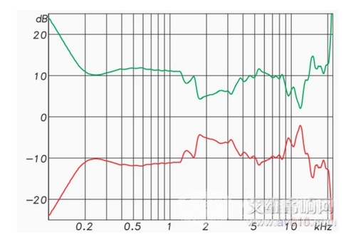
Figure 8
This has a huge impact on the balance work. The “corrected†FIR filter has the following characteristics:
1. The amplitude and phase response of the speaker is completely flat.
2, can correct abnormal reflections in the room and space, such as the boundary effect near the speaker.
3. Process the components of the speaker array separately to improve the line array response. Beam shaping and steering can be done, which is not possible with analog filters.
The FIR can be convolved with the program material and used as a filter. Many DSPs currently support FIR filters , allowing IR to be real-time convolved with program material. Using FIR filter equalization at some point in space makes "perfect speaker response" possible. Since there are no two points in the space with the same IR, the "corrected" area cannot be extended. But this does not mean that FIR equalization is useless, it also has a "push back" effect, which can create a more perfect listening experience.
We draw the following conclusions:
1. The FIR can change the amplitude response of the speaker without changing its phase response. This linear phase behavior requires sacrificing delay.
2. Any measurable impulse response can be used as an FIR filter , allowing monitoring of indoor data such as GratisVolver or performing proper equalization. Even the echo cancellation of the conference room system can be performed in real time.
3, using convolution, FIR can be implemented in software, such as using GratisVolver to monitor room impulse response.
4, FIR can be implemented in hardware for real-time signal processing. Some DSPs currently support a specified FIR filter .
An audio filter is not just an integration of capacitors, inductors, and resistors. It can be generated by mathematical algorithms or measurements, or it can be implemented in real time using digital signal processing techniques.
Commercial Semi-hermetic Screw Compressor Sight Glass Sight Glass
Shenzhen Capitol Micro-Electronics Co.,LTD , https://www.capitolgtms.com