Design of Vehicle Super Capacitor Test System Based on Single Chip Microcomputer
With the advancement of technology, electric vehicle technology has developed rapidly. Compared with internal combustion engine vehicles, electric vehicles have the advantages of zero emissions, high energy efficiency, low noise, low heat radiation, easy handling and easy maintenance, which will be the direction of future automobile development and a hot spot of current research.
There are three types of power batteries for electric vehicles: fuel cells, batteries, and super capacitors. Fuel cells, batteries and supercapacitors are complementary in energy density and power density [1]. A single battery, fuel cell or super capacitor is difficult to use as a power source for electric vehicles. Hybrid batteries are an ideal solution. Hybrid battery drive system, especially the use of super capacitors for rapid charge and discharge can achieve vehicle braking energy recovery, and the fuel cell's large energy density supports the car's long-term driving, making the hybrid drive system composed of fuel cell/super capacitor the best for electric vehicle drive. Scenario 2].
For automotive power supplies, in order to achieve higher power and energy, supercapacitors often use multiple modules in series. With the increase of the capacitor cascade, the overall voltage of the battery also increases; for the vehicle battery, the working voltage of the super capacitor often reaches several hundred volts, and the fluctuation caused by such a high peak voltage will bring strong electromagnetic interference, which is a capacitor component. The detection brings great difficulties. At the same time, since the series super capacitors are often charged and discharged with a large current (usually between 50A and 150A), the voltage and current change very rapidly. For example, when a medium-sized passenger car uses a super capacitor to discharge at a current of 150A, the terminal voltage will be reduced from 300V to 70V in one minute, and the current will increase from 50A to 150A in a few minutes at 200V constant voltage. The noise impact caused by the speed and amplitude of charging and discharging is also very large.
For the special working condition of super capacitor, this paper presents a super capacitor battery detection system. Through the charge and discharge cycle test of the super capacitor assembly, the voltage and current parameters are collected and compared with the standard parameters to verify that the detection system can quickly achieve higher detection accuracy under the condition of strong voltage and current changes.
1 detection system principle and implementation of each module
1.1 Test object The test super capacitor uses two sets of series asymmetric electrode double layer super capacitor components provided by Shanghai Aowei Technology Development Co., Ltd.
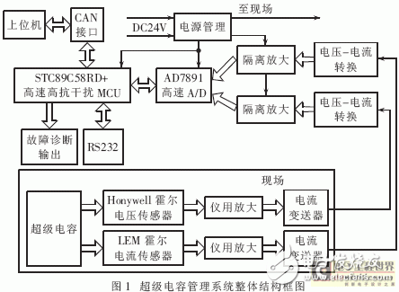
1.2 Introduction to System Principle The super capacitor management system can realize real-time acquisition of super capacitor working current and voltage. The overall structure block diagram of the super capacitor management system is shown in Figure 1. The system consists of three main modules: field voltage, current, acquisition and conditioning module (ie acquisition module), signal isolation and MCU signal processing module (ie central processing module), power management module. In the acquisition module, the Hall voltage and the Hall current sensor respectively collect the supercapacitor voltage and current in the field, and the collected signal is amplified by the instrument, and then converted into a 4 mA to 20 mA current signal and sent to the central processing module. In the central processing module, the 4mA~20mA current signal sent by the acquisition module is subjected to current and voltage conversion, then is isolated and amplified, AD converted and sent to the MCU; the MCU processes the data and transmits it to the host computer through the CAN interface; when the data is detected; When abnormal, the MCU outputs a fault signal so that the staff can take immediate action. The power management module provides a stable isolated voltage for each functional module. Add RS232 communication serial port for MCU program to burn.
1.3 Implementation of each main module The test system uses four circuit boards to realize three major functional modules—the acquisition module, the central processing module and the power management module. That is, voltage acquisition and initial conditioning board, central processing board and power board. The following focuses on the implementation of the voltage, current acquisition module and central processing module.
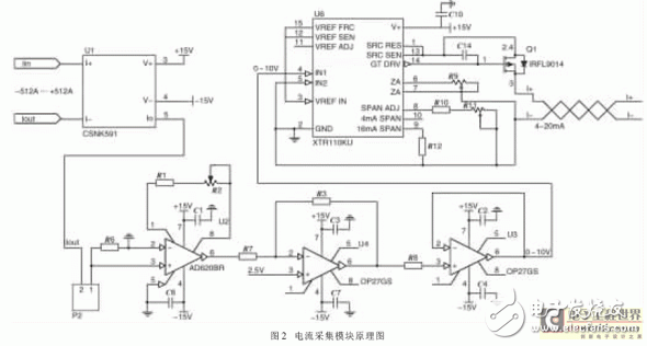
1.3.1 Implementation of the acquisition module The acquisition module includes the acquisition of bus current and the acquisition of bus voltage. Figure 2 is the schematic diagram of current acquisition. The Hall current sensor is used to isolate the system under test, which has higher precision, better safety performance and stronger anti-interference ability than the traditional current-separating circuit based on resistance sampling. In this paper, Honywell's Hall closed-loop current sensor CSNK591 based on magnetic compensation principle is used. The measurement range is ±1200A, the linear precision is 0.1%, the overall accuracy is 0.5%, and the response speed is less than 1μs, which fully meets the requirements of the system. The acquisition signal is converted into a voltage signal by a precision resistor, and then amplified by the instrument amplifier into a ±5V bipolar voltage signal. The system uses the amplifier chip of AD620BR instrument. The chip has a large common mode rejection ratio when the gain is low (the common mode rejection ratio is 100dB when G=10), which can strongly suppress the temperature, electromagnetic noise and other factors. Common mode interference caused. The amplified signal is raised to 0~10V unipolar signal through the OP27GS chip, sent to the transmitter XTR110KU through the emitter follower, and converted to a current signal of 4mA~20mA to the central processing module. The reason why the acquisition signal is converted into a 4 mA to 20 mA current signal is considered to be unified with the industrial interface standard, and the current transmission is highly resistant to interference.
The bus voltage is also collected using the closed-loop Hall voltage sensor VSM025A based on the principle of magnetic compensation. The principle is the same as the current acquisition.
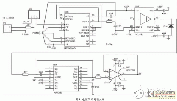
1.3.2 Central Processing Module Implementation The central processing module is the core part of the test system, including MCU and AD unit, analog signal secondary conditioning unit, fault output unit and CAN interface unit, as shown in Figure 3.
The 4mA~20mA current signal input by the acquisition module first passes through the analog signal secondary conditioning unit to perform signal transmission, isolation, filtering and amplification. There are many ways to isolate analog signals. The commonly used methods are isolation amplifiers, linear optocouplers, and voltage-to-frequency conversion. The isolation amplifier and linear optocoupler have high isolation voltage, strong anti-interference ability, and high linearity, but the linear optocoupler isolation circuit is complicated. There are many parameters that need to be adjusted, and when the input voltage is relatively small, the linearity is poor. Therefore, this paper selects BB's high-precision ISO124U isolated operational amplifier to complete the isolation of the input analog signal. The isolated signal is filtered by the 5th-order Butterworth low-pass filter MAX280 circuit to filter the high-frequency interference, and then sent through an emitter follower.
The acquired signal after the second conditioning is sent to the MCU via the 12-bit high-speed AD7891. The MCU processes the data and transmits the data to the host computer via the CAN interface. The single-chip microcomputer selects STC series 8-bit high-speed single-chip STC89C58RD+. The MCU has strong anti-interference, 4kV fast pulse interference (EFT) and high anti-static (ESD), and can pass the 6000V static electricity, which satisfies the working environment of super capacitor high voltage and high current. The MCU can realize 6 clock mode. In the case of 24M crystal oscillator in this system, the working frequency of MCU can reach 4MIPS, which is equivalent to 4 times of the running speed of ordinary 51 series MCU.
In addition, the test system sets the 3-channel fault diagnosis output, which can display the status of undervoltage, overvoltage, overcurrent, etc. The test system and the host computer adopt a CAN communication method with strong anti-interference ability and good stability to ensure the reliability of the data sent by the test system to the host computer.
The actual system has analog ±15V, digital ±5V, analog ±12V power supply requirements, the power management module provides analog and digital circuit isolation while providing the required voltage for each part of the system, thus avoiding the interaction of the two types of voltages. TVS protection is added to each part of the power inlet to prevent damage to the system from surge voltage. At the same time, corresponding filter circuits are set at many power inlets, for example, a π-shaped filter circuit is added at the AD power supply inlet to better eliminate the interference of the power signal to the supplied circuit.
In addition, the external wiring is shielded, which can shield the electromagnetic interference in the transmission. All current plates are packaged in profiled aluminum boxes and wired to the outside world using standard aerospace connectors to protect the circuit board while isolating the external magnetic field.
2 Test system comparison and analysis of measured results
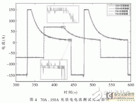
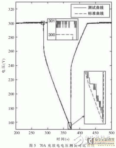
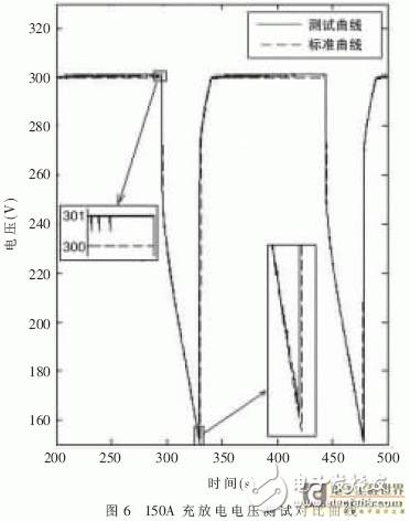
2.1 Test Content The experiment selected to charge and discharge the two series of super capacitor components in series of 70A and 150A. First, the capacitor is subjected to constant current charging. When the bus voltage reaches 300V, it is switched to constant voltage charging. When the bus current is reduced to 10A, 70A constant current discharge is performed, and the cycle is tested for 5 cycles.
2.2 Experimental Results and Analysis Figure 4, Figure 5, and Figure 6 show the comparison of test curves in two cases. Among them, Figure 4 shows the current curve of the two standard test cases 70A and 150A. Figures 5 and 6 show the voltage curve characteristics in two cases. It can be seen that the match between the two is very good. The voltage test accuracy is higher than the current test accuracy. This is because on the one hand, the voltage of the charge and discharge system itself is higher than the current control accuracy. On the other hand, the current sensor is placed in the capacitor case and close to the single capacitor, and the noise generated when the capacitor is charged and discharged. The interference is more serious. At the same time, the Hall current sensor has a large aperture, and there is still a certain gap after passing through the current bus, which affects the test accuracy to some extent. Comparing the current curves of each group, it can be seen that as the current increases, the relative error of the test results decreases, but the absolute error remains consistent, not exceeding 3A.
This paper presents a vehicle supercapacitor test system. The system uses a closed-loop current and voltage sensor based on the magnetic compensation principle to collect the bus signal. The STC51 high-speed single-chip microcomputer is used for signal processing against high-voltage pulse interference, and the instrument uses amplification and current. Transmission, analog signal isolation, 5th-order low-pass filtering and other measures to reduce the noise of the signal transmission process as much as possible. Through the charge and discharge test of the super capacitor assembly, it shows that the system has the advantages of strong anti-interference ability and high detection precision, and can well meet the test requirements of the vehicle super capacitor high voltage and high current environment.
Motorola Radio,Motorola Two Way Radios,Motorola Talkabout Radios,Motorola Handheld Radio
Guangzhou Etmy Technology Co., Ltd. , https://www.digitaltalkie.com
