Design of Network Video Compression System Based on Blackfin
Summary:Using the video decoder chip ADV7183A to complete the acquisition and quantization of analog video signals, and then the video data is compressed by ADSP-BF561, and then the compressed video data is transmitted to the network composed of chips such as ADSP-BF537 and LAN8187 through PPI transmission. The transmission module, the network transmission module sends the processed video data stream to the designated user through multicast and unicast. It can meet the real-time and remote requirements of the FM monitoring system.
Key words: BF561; ADV7183A; video compression; network transmission
With the development of the video society and the advancement of technology, video information services have grown rapidly. Video information technology has undergone a transition from analog to digital. Digital video is recorded in digital form. Digitalization has created and transmitted video information. Advantageous conditions, but the processed digital video stream has a higher bandwidth, so under the condition of ensuring the clarity, smoothness and real-time of the video image, video reduction and network transmission become an important technology.
1 Design scheme The structure of the network video compression hardware system is shown in Figure 1. In this network video compression system, Analog Devices' ADSP-BF561, ADSP-BF537, ADV7183A core chip; SMSC's LAN8187 network chip; the system can be divided into video capture compression module and network control module, of which video capture compression module It consists of ADI high-performance dual-core processor DSP BF5 61 and video decoder chip ADV7183A, supplemented by peripheral devices such as SDRAM and Flash. The network control module consists of ADI high-performance DSP BF537 and Ethernet interface chip LAN8187, which is also supplemented by peripheral devices such as SDRAM and Flash. The analog video signal input at the front end is quantized and converted into a digital video signal by the video decoding chip ADV7183A, and enters the buffer storage area of ​​the BF561 through the parallel PPI interface of the BF561, and the compression processing of the 觎 frequency data is completed by the BF561, and the MPEG4 video stream formed by the compression passes through the parallel The PPI interface enters the BF537 and is encapsulated and distributed through the Ethernet interface.
This article refers to the address: http://

2 hardware circuit design
2.1 Video Acquisition Compression Module Design The video acquisition compression module consists of the core compression processor BF561 and the front-end video decoder ADV7183, supplemented by peripheral SDRAM and Flash.
(1) Video compression processor BF561. The BF561 processor is a high-performance product in the Blackfin family. The core of the BF561 consists of two independent Blackfin processors. The BF561 integrates a common set of digital image processing peripherals to create a complete system-level on-chip solution for digital image processing and multimedia applications. Using the BF561 dual-core structure, the video signal collected by the front-end video decoder is divided into upper and lower field data, and the divided video data is separately compressed by its dual core, so as to completely restore the picture before compression, between the dual cores Synchronization processing is performed, so that the decoded pre-compressed picture can be completely and smoothly recovered according to the output data information, and at the same time, the balance of the two core workloads, and the initialization of the system and the control of the front-end video decoder are handed over to the main core. Processing, superimposing the dynamic auxiliary information on the video screen is handed over to another kernel for processing.
(2) Video Decoder ADV7183A The ADV7183A is an enhanced video de-M encoder integrated with a 10-bit ADC from Analog Devices, Inc. (ADI). It contains three precision analog-to-digital converters (ADCs) and a complete automatic gain control (AGC) circuit. Its flexible digital output interface seamlessly interfaces with the BF561's PPI interface, eliminating the bottleneck of overall compression processing due to data transfer speed. The configuration communication between the ADV7183A and the DSP follows the I2C protocol, so the ADV7183A provides a standard I2C interface that interfaces with the PF interface of the BF561.
The PF of the BF561 is connected to the 0E pin of the ADV7183A to control the data output of the video decoder. The output data here can select 16/8-bit output, and the system selects the 8-bit output data format.
The PF2 pin of the BF561 is connected to the SDATA pin of the ADV7183A. The SDATA pin of the ADV7183A is the serial data input/output pin of the I2C bus.
The PF0 pin of the BF561 is connected to the SCLK pin of the ADV7183A. The SCLK pin of the ADV7183A is the serial data input/output pin of the I2C bus, providing a serial clock input for the video decoder.
The PPI2CLK pin of the BF561 is connected to the LLC1 pin of the ADV7183A, and the video pixel output synchronous clock is provided by the LLC1 pin of the ADV7183A for the BF561.
The PF13 pin of the BF561 is connected to the RESFT pin of the ADV7183A to provide a reset signal for the video decoder.
The PPI2D0~7 pins of the BF561 are connected to the P8-P15 pins of the ADV7183A as a video data transmission bus.
At the same time, the ADV7183A is provided with a 27 MHz crystal input column XTAL pin. The analog input channel AIN1 is selected and the analog signal is input on the AIN1 pin. For the system, the default configuration is adopted, and the I2C bus is no longer configured. After completing these settings, connect the power supply, ADV7183A can be done under the default configuration, the default input is PAL image, the output is P8 ~ P15 8-bit ITU-BT656 YCrCb type 4:2:2 video data.
2.2 Network transmission module design The network transmission module is the channel that sends the output data stream processed by the video acquisition compression module to the external user. Therefore, the core processing processor is required to be easily connected with the BF561 and has good network expansion. Sex, so I chose the same series of BF537 processors to make full use of its PPI interface to achieve fast and seamless connection with BF561. Since BF537 integrates Ethernet MAC controller, it can also use BF537 network to expand performance, supplemented by SMSC. The company's Ethernet interface chip LAN8187, while LwIP (Lightweight TCP/IP Stack, lightweight TCP/IP stack) effectively reduces the space occupied by the TCP/IP protocol stack, LwIP occupies about 40 kB of memory space and ROM The storage space is much smaller than the TCP/IP protocol stack implemented in the kernel, and LwIP supports IP forwarding under multiple network interfaces, supports ICMP protocol, supports extended UDP packets, and supports forwarded TCP packets. A dedicated internal callback interface (RawAPI). The RAW API directly uses the Call Back Functions in the LwIP stack, allowing applications and protocol stack code to be better integrated and run in the same process to improve application performance and fit For the needs of embedded systems.
The SDRAM in the system is mainly used to load the system program and open the storage buffer of the video data information, and the Flash is used to program the system loader after the debugging is completed. They are extended by the external bus interface unit (EBIU) of the core processors BF561 and BF537.
3 system software design
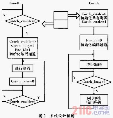
3.1 Video Acquisition Compression Module Video Acquisition Compression Module: Since BF561 is a dual-core processor, in order to make full use of its dual-core structure to improve video compression capability, in the software design of this module, the system workload is rationally distributed, the system After power-on, first initialize the system in its main core, set the working frequency multiplication of the system, configure the front-end video decoding chip ADV7183A, manage the communication transmission with the front-end video decoder, and then enter the loop to wait for the video compression. The command, while the other core is also in the waiting state, after receiving the video compression start command, the video data collected by the front end is divided into upper and lower field data in the main core, and respectively delivered to the dual core for compression processing, to ensure that each The integrity of the video data after one frame compression adopts the semaphore synchronization method before and after the compression of each frame of video data, ensuring the synchronization of the dual-core work and the integrity of the video data output, and the video capture compression processing part program flow as shown in picture 2.

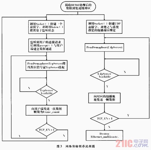
3.2 Network transmission module Network transmission module: The network transmission module is mainly responsible for the interaction between the system and the user, including receiving user commands and providing video data streams to users, wherein providing data streams to users includes transmitting video data and providing multicast. Two ways of service, after each compression of the frame data, the video capture compression module reminds the BF537 to read the compressed video data in DMA mode by means of interruption, for users who require strict data transmission stability and reliability. The network transmission module sends the read video data to the designated user in the transmission mode of the TCP. For the user mainly based on the local area network, the number of users is uncertain, and the transmission stability and reliability requirements are not very high, the network transmission module The DP video transmission method is used to transmit the read video data to the group members in the multicast, and the multicast method is also used to save network bandwidth resources. In order to prevent the coordination between receiving video data and transmission in the system work, the semaphore method is used to constrain the logic of receiving and transmitting data, preventing the problem of sending duplicate data or null data. The program flow of the network transmission module is as shown in the figure. 3 is shown.

4 Conclusion Network video compression system uses the core processor BF561, BF537 and peripheral chips to complete the functions of video information collection, compression processing, network transmission, etc. It can meet the real-time and remote requirements of the video surveillance system, providing unicast and group. Two different remote monitoring methods are broadcast.
Hongkong Onice Limited , https://www.ousibangvape.com