Conquer bridge technology and improve the design of vehicle laser projector
The display and information systems in the car are very rich, surrounded by us, some information is very important, some for comfort or entertainment, and some just provide information, which is valuable, but not necessary. As a driver, what we need most is critical data about the car's working conditions – and it's real-time. Automakers use a variety of technologies to provide drivers with such critical information, including discrete LEDs, dashboards and liquid crystal display technology. Although the model of each car is different, the way information is provided is very consistent, and almost every occupant can quickly adapt to and get information from unfamiliar models. In addition, these data and information can also be virtually projected into the line of sight of the driver in front of the vehicle using a heads up display (HUD) system. With the continuous development of display technology, HUD has become very popular in luxury cars. With the reduction of cost, size reduction and performance improvement, these HUD systems are also being adopted by mid-range cars and will soon be popularized in economy cars.
The latest HUD technology uses mobile MEMS mirrors and color lasers, so-called miniature laser projectors. These laser projectors offer the advantages of infinite focus, clear sunlight, superb color saturation and small size, making them ideal for automotive infotainment systems. This paper proposes a new scheme using a miniature laser projector by analyzing the modern HUD technology in the automotive field. The integrated "bridge chip" solution uses a high-performance three-channel laser driver that reduces size, cost, and design complexity compared to older TFT, CRT, and DLP technologies, all thanks to the laser.
HUD technology foundation
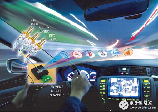
At the heart of the latest HUD technology is a miniature laser projector (Figure 1), a small MEMS imaging system that projects a pixel array onto almost any surface. Micro-laser projectors do not use radiation technology (TFT and CRT), but instead emit a bundle of colored light to draw images, meters and indicators. The beam scans a raster image similar to a CRT TV. Each pixel is produced by a combination of chromaticity and brightness of the three primary colors (see Figure 1).

Figure 1. The core of the pico projector is the R, G, and B lasers, as well as the moving MEMS mirror.
Using the MAX3601 laser driver's integrated 8-bit DAC, each pixel produces 24-bit full-color RGB colors, resulting in 16 million unique colors. Because the laser emits each color at a very different frequency, it is brightly colored and can be "oversaturated" to attract the driver's attention. In the woods or jungle environment, the green color is deliberately highlighted to highlight.
The combined beam is sent to a scanning MEMS mirror chip which produces a scan line by horizontal scanning and then longitudinally ramped to combine the scan lines into a display surface. The resulting high-definition image is refreshed at 60 Hz and is always in focus – another advantage of laser technology, especially for curved automotive windshields.
The challenge of driving micro projectors
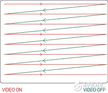
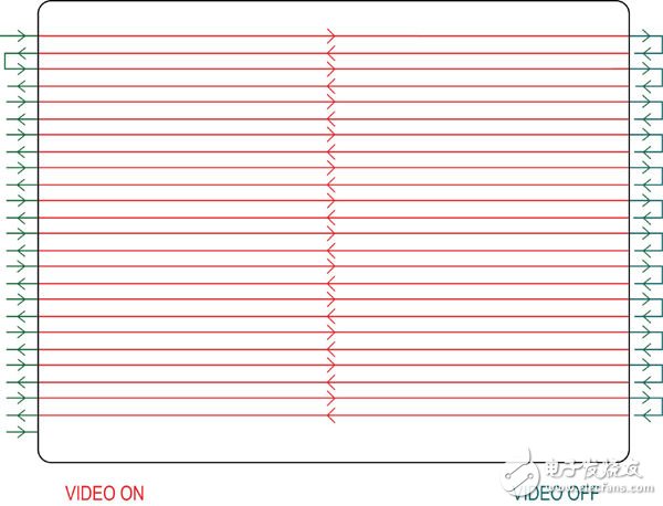
In a cathode ray tube (CRT), each scan line starts from the left and is quickly returned to the start of each line using a flyback method (Figure 2). With modern digital technology, the miniature laser projector scans odd lines in a forward direction and scans even lines in a reverse manner (Figure 3).

Figure 2. During the blanking of the CRT, the beam is turned off and the retrace returns to the next line.

Figure 3. For a pico projector, the laser turns on when drawing each line from left to right; then turns off in the inactive video area that falls vertically; when the active video is drawn from right to left, the laser turns on again.
Another difference between CRT and microlaser projector technology is the timing variation, which depends on the position of the pixel on the horizontal scan line. Because of the MEMS technology, the mirror must accelerate and decelerate at the beginning and end of each line. Due to the inertia of the MEMS mirror, it slows down before reaching each end, thus forcing pixels sent with a constant pixel clock to "push up" at the end. If left uncorrected, this pixel sticking phenomenon will show high edge brightness and coordinate distortion from left to right (Figure 4).
90W Solar Panel,90W Polysilicon Solar Panel,60W Polysilicon Solar Panel,80W Polysilicon Solar Panel
Zhejiang G&P New Energy Technology Co.,Ltd , https://www.solarpanelgp.com