Analysis of the design and application prospect of low noise amplifier on mobile phone GPS
Recently, it was reported that Nokia announced a high-profile version of Ovi Maps for its smartphones, which will include high-end walking and driving navigation. This move is regarded as a tremendous change that has an impact on the GPS mobile phone navigation industry and GPS navigation related industries. With the general improvement of mobile phone performance and the solution to the unique problems of mobile phone GPS receivers, the GPS function is no longer the exclusive configuration of high-end mobile phones, and it is developing to the standard configuration of ordinary mobile phones.
GPS function introduction
GPS is called Global Positioning System. It consists of 24 satellites distributed in 6 orbits at different heights. There are navigation and positioning according to function; military and civilian according to application. Among them, the military frequency is 1.227GHz, which is exclusively used by the US military. It is mainly used for weapon guidance, reconnaissance and other military and war purposes, with high precision. The civilian frequency is 1.575GHz, which is free for global use. The purpose is mainly used in the field of HNA and the natural sciences. More widely, we are familiar with car navigation. Only the valid signals of 3 stars can be received at the same time to determine its position.
The GPS signal is weak and the receiver sensitivity is usually around -136dBm.
The challenge of mobile GPS
The characteristics of mobile phone applications: small size, low power consumption, good productivity, cheap devices, short design time, and fast market time. The GPS function based on the mobile phone platform has higher requirements and more challenging than the independent GPS receiver. It mainly considers the following aspects: electronic environment, power consumption, volume, price, convenience in design and easy realization of performance indicators Sex.
The common single-chip GPS receiver uses CMOS technology, which cannot achieve high receiver sensitivity. Compared with the car driving on the road in a wider space, the handheld GPS is more flexible than the vehicle's movement, the position signal will be weaker, and multipath reception is more common. It is required that the receiving ability is stronger, and it is necessary to add filters and low noise amplifiers in the receiving front end.
GPS design considerations on mobile phones
The electronic environment is even worse. GPS receiving and mobile phone power are placed on the same board. For 1.575GHz GPS signals, the main out-of-band signals are: 900MHz, 1800MHz GSM power amplifier; 1800-1900MHz PCS power amplifier; 2.4GHz WLAN, Bluetooth; and 2.5-2.7 WiMAX in GHz. Although these signals will not exist at the same time, each is very strong and has a significant impact on GPS reception performance. Experiments show that: -15dBm out-of-band signal will cause the GPS low-noise amplifier gain to drop by 1dB. Therefore, when choosing a mobile phone GPS low-noise amplifier, not only should look at its own noise figure and gain, but also pay attention to its out-of-band attenuation index, which It is very important to the GPS receiver's capturing ability, tracking performance and positioning accuracy, and even whether it can work normally.
CDMA and WCDMA mobile phone transceivers work in duplex mode. The transmitted signals and noise of their power amplifiers can interfere with GPS signals or even block them. Therefore, the GPS receiver must add an LNA and a high-performance filter. LNA increases its receiving sensitivity, while the filter enhances out-of-band attenuation. Another benefit to the design and wiring is that the LNA can be placed close to the antenna end, reducing the requirement for the location of the GPS receiver module and improving the noise figure of the GPS receiver by about 1.5dB. However, because GSM mobile phone transmission and reception work in a time-division manner, relatively speaking, the out-of-band attenuation requirements for GPS signals are not very stringent. You can save high-performance filters and use simple filtering and low-noise amplifier solutions to achieve GPS receiving front-end To save costs.
For different systems and platforms, there are currently several solutions for mobile phone GPS receiving front end:
-On the GMS system, choose an active antenna, that is, low noise amplifier and GPS receiving antenna are integrated;
--In CDMA, WCDMA systems, there are separate low-noise amplifiers and filters, and the materials and performance of the two devices have choices. The above scheme is a challenge to design time, design difficulty, performance indicators, PCB size, and component count.
As the market demand changes, the GPS receiver front-end with integrated filter and low-noise amplifier has been widely used, and its benefits are obvious. Like discrete devices, there are different combinations of the two: LNA + ceramic filter or LNA + SAW (surface acoustic wave filter). In the market, CaAs E-pHEMT + FBAR scheme is the best performance: low noise, better linearity and better out-of-band attenuation.
Avago is committed to GPS receiving front-end modules
Avago combines the industry-leading CaAs E-pHEMT process and FBAR filter technology to provide GPS RF front-end series modules, which provide a variety of options for GPS plus low-noise front-end. See Figures 1, 3, 4, and 5 for details. Structure There are: Filter + LNA + Filter; Filter + LNA; LNA + Filter; or simple LNA, Avago has fully considered its application environment when planning and designing these products, and is the first choice for mobile phone GPS receiving design.
Characteristics of CaAs E-pHEMT low noise amplifier
Compared with other materials and processes, the advantages of CaAs E-pHEMT are mainly: low noise figure, is the first choice for low noise amplifier; high linearity at low operating voltage, improve receiver dynamic range, is conducive to subsequent signal mixing and demodulation ; High gain is the value of the amplifier. Therefore, CaAs E-pHEMT is the perfect combination of three important indicators of noise figure, linearity and gain, which is difficult for Si materials to achieve.
Features of FBAR filter
Ceramic filter can withstand larger power, good temperature characteristics, but the volume is large, the Q value is not as good as FBAR;
SAW filters withstand low power, poor temperature, low Q value, and low cost. There are applications on some mobile phones with low requirements;
FBAR filter: good performance, small size, easy to integrate. With the use of duplexers in mobile phones, filters have replaced SAW more and more, and their cost performance has been recognized by everyone.
ALM-1712 GPS receiving front-end example
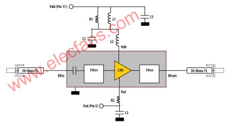
Figure 1 below shows Avago's ALM-1712 product, which is composed of two FBAR filters and an LNA. The total noise figure of the three stages is 1.65 dB. ESD> 3KV on the RF side, eliminating the need for additional ESD protection devices, saving space and cost. Working as low as 1V, the turn-off function meets the low power consumption requirements of mobile phone applications, and the variable bias provides an ideal balance among various performance indicators. The package is 4.5 (L) x2.2 (W) x1 (H) mm3, and the peripheral devices only have 8 resistors, capacitors and inductors.

Figure 1: Avago ALM-1712 product
The following figure 2 shows that the gain at 1.575GHz is 12.8 dB at Vdd = 2.7V, Idd = 8.0mA; linear IIP3 = +7 dBm, IP1dB = +3 dBm, and the 900MHz out-of-band attenuation is up to 95dBc, The out-of-band attenuation of 1800MHz is up to 90dBc, which effectively guarantees that the GPS receiver can play a good function in the harsh electronic environment. ALM-1712 satisfactorily meets the special requirements of mobile phone GPS: electronic environment, power consumption, volume and cost requirements, design time and performance indicators, which are self-evident for mobile phone manufacturers.

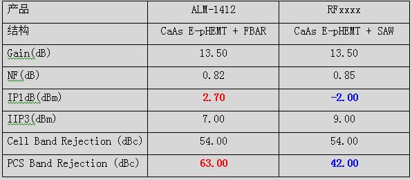
The following are the main indicators of the two common models in the market. In the case of low noise amplifiers using the CaAs E-pHEMT process, it is not difficult to see that the FBAR filter's suppression of the PCS band is 21dB higher than SAW (63 vs. 42)

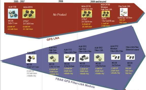
Figure 1 is the development roadmap of Avago's GPS receiving front-end product line. It is not difficult to find that Avago attaches great importance to the GPS receiver front-end module and low noise amplifier market. With the wide application of different functional performance products in GPS receivers, Avago will continue to launch more products that meet the market. For details, please consult Avago Asia Pacific Shiqiang Telecom, an important regional agent.

Figure 1: Avago Technology GPS receiving front-end product development circuit diagram
For the GSP, ISM and WiMAX markets, Avago recently launched the MGA-24106 low-noise amplifier, which inherits the advantages of Avago low-noise amplifier products that have the usual noise figure, gain and linearity. Under the bias of 3.3V6mA, 1.57GHz, the noise figure is 0.87, the gain is 19.6dB, the IP1dB is -8.7dBm, and the IIP3 is -0.2dBm. It can work normally at a voltage as low as 1.8V. Packaged in 1.5x1.2x0.5mm3, only a few peripheral devices are needed. In terms of volume, power consumption and low voltage operation, it is more advanced, and its price is more competitive in the market. In handheld, mobile terminal wireless devices have broad application prospects.
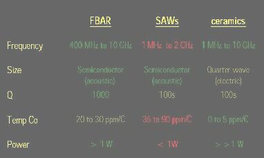
Figure 2 shows the performance comparison of FBAR, SAW and ceramic filters for mobile phones. FBAR technology is another leading technology product line of Avago. Duplexers, multiplexers and various filters on mobile phones all occupy a large share. (Shiqiang Telecom)

Figure 2: Performance comparison of FBAR, SAW and ceramic filters
The magnetic buzzers (Self-drive Type) offer optimal
sound and performance for all types of audible alert and identification. Our
Magnetic Buzzer solutions are offered with various mounting options. We also
provide you with a washable version for your preferred soldering method. Our magnetic buzzers, also known
as indicators, are designed with an internal drive circuit for easy application
integration. During operation, current is driven through a voice coil to
produce a magnetic field. When a voltage is applied, the coil generates a
magnetic field and then allows the diaphragm to vibrate and produce sound. This
Buzzer type has a low operating voltage ranging from 1.5 – 12V+. Our magnetic
buzzers are desirable for applications requiring a lower sound pressure level
(SPL) and frequency.
Magnetic Buzzer Self-drive Type
Passive Buzzer,Dc Magnetic Buzzer,Electro Magnetic Buzzer,Magnetic Buzzer Self Drive Type
Jiangsu Huawha Electronices Co.,Ltd , https://www.hnbuzzer.com