Accurate compensation method for temperature drift error of cylinder pressure real-time monitoring system
With the development of modern science and technology, the performance of special vehicles is getting higher and higher, the system composition is more and more complex and precise. Real-time online monitoring of many working parameters is realized by embedded sensors, which is the development of vehicle condition monitoring and fault diagnosis system in the future. The inevitable trend [1]. At the same time, due to the compact structure of the vehicle, a small embedded sensor monitoring system is required. Otherwise, many fault points cannot be directly monitored, and can only be obtained by measuring peripheral related parameter conversion. The correctness of the conversion result is unknown, which may lead to greater economic loss. With the development of microelectronics and signal processing technology, the realization of small pressure monitoring systems has become possible. This paper adopts advanced pressure sensor device, combined with precision amplifying circuit and low-power high-performance processor to form a real-time monitoring system for the operating pressure of embedded special vehicle planetary shifting mechanism, and realizes the monitoring system through the comprehensive application of measuring circuit and compensation algorithm. High precision error compensation.
This article refers to the address: http://
1 Implementation of soft and hard compensation method for embedded pressure monitoring system
1.1 Introduction to Pressure Monitoring System
The planetary shifting mechanism of the special vehicle is located in the large box of the integrated transmission, and the surrounding space is narrow and partially immersed in the lubricating oil at a temperature of up to 135 °C. Through demonstration, a small isolation diaphragm pressure sensor was selected and installed on the oil passage of the cylinder accessory. The signal was amplified by a precision instrumentation amplifier and quantified by a high-signal analog-to-digital converter (ADC). The data processing is completed by ATMEL's AVR series microcontroller (MCU) [2], and the processing result is provided to the operator through the CAN2.0 bus to achieve the purpose of protecting the vehicle integrated transmission. The system block diagram is shown in Figure 1.
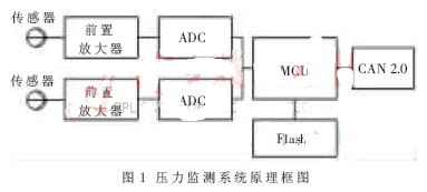
Since the operating temperature range of the system is relatively wide (-20 °C~135 °C), the temperature variation has the greatest influence on the measurement error of the system. This paper focuses on the research and implementation of the compensation method for measurement error caused by temperature drift [3]. The compensation method of the whole system includes two parts: circuit hard compensation and algorithm soft compensation. The hard compensation includes the process modulation compensation and amplification circuit compensation of the sensor itself; the soft compensation is realized by embedding the B-spline temperature compensation algorithm in the MCU.
1.2 Hard compensation circuit design
The system adopts a silicon piezoresistive pressure sensor, which has the characteristics of small volume, high sensitivity and high resolution, and is widely used. However, temperature drift is the biggest weakness of silicon piezoresistive sensors, including zero temperature drift and sensitivity temperature drift. Since the resistances of the four resistors that make up the bridge cannot be exactly the same, when the input pressure is zero, the bridge output is not zero and has a zero offset. Sensitivity temperature drift is mainly caused by the change of the piezoresistive coefficient of semiconductor materials with temperature. Generally speaking, the sensitivity of piezoresistive sensors decreases with increasing temperature [4].
This system uses a small silicon piezoresistive sensor from a US company with a maximum range of 300 psi (1 psi = 6.895 kPa), an output voltage of 0 to 100 mV, and a nonlinearity of ±0.1%. The sensor achieves temperature compensation and zero offset adjustment of the sensor by laser trimming the thick film resistor on the ceramic base. The laser correction resistor provided inside is used to adjust the gain of the external amplifier to ensure the ±0.1% interchangeability range of the sensor. The circuit schematic is shown in Figure 2.
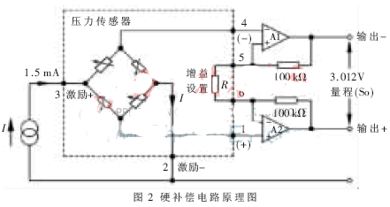
Since the minimum resolution of the sensor is microvolts, it is easy to cause interference during transmission and measurement, resulting in distortion of the result. Therefore, a high-precision, high-common-mode rejection ratio measurement amplification circuit must be used for small signal amplification.
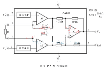
The system uses an instrumentation amplifier INA128 with differential input and closed-loop gain unit as the front-end amplifier circuit for hard compensation. The two inputs of the instrumentation amplifier are balanced and have high resistance, low input bias current, low output impedance, and 100 dB common-mode rejection, reducing any error in common-mode levels. Up to 100 dB. Its internal structure is shown in Figure 3, which coincides with the amplifier in the hard compensation circuit shown in Figure 2.
1.3 Soft compensation algorithm implementation
After the system is hard compensated, the voltage signal is sampled by a 24-bit quantized analog-to-digital converter (ADC) and sent to the MCU for subsequent processing. The MCU adopts ATMEL's ATmega32, and its data throughput rate is up to 1 MIPS/MHz. Using the data processing capability of the MCU, the B-spline based temperature drift compensation processing algorithm is realized. The B-spline curve is used to fit the temperature coefficient of the pressure sensor because the B-spline curve has local control characteristics, and the curve only changes shape near the changed control point; and the B-spline curve can be added and controlled at will. Points, without increasing the order of the curve, can be used to select different control points for different applications [5].
The spline is a piecewise polynomial function, and the expression for the kth order (k-1) B-spline curve is:
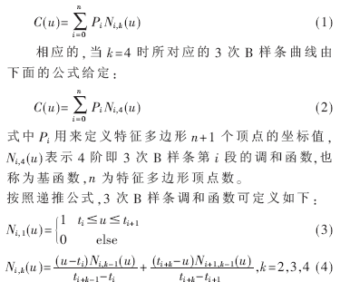
When the denominator is zero, the value of the defined fraction is zero. Where ti represents the control point node value, which controls the shape of the curve, and the node value is from t0 to tn+4. The non-closed curve is used in this system, so the ti value rule is as follows:

The B-spline-based compensation algorithm is implemented in the MCU. Considering that the B-spline is a non-closed curve, the selection of the control points by equations (4) and (5) should be more than four. Considering the real-time nature of the compensation algorithm, certain requirements are also imposed on the calculation speed, and the control points should not be too large. Based on the above reasons, take n=6, sample the sensor data, and calculate by the single-chip computer. According to the calculation formula of the B-spline curve, derive the control node value ti, and write the solution of the B-spline harmonic function for 3 times. A control point calculates a compensation coefficient C(u) and writes the compensation coefficient to the corresponding Flash register. When the system is working normally, the temperature value of the pressure monitoring system is obtained by the vehicle temperature sensor, and the compensation coefficient of the corresponding register is read, and the measured value is compensated to obtain the corrected pressure output.
2 soft and hard compensation method experimental results
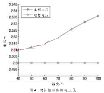
During the experiment, the pressure sensor was placed under a constant pressure of 150 psi to measure the amplified output voltage of the pressure sensor signal. If the system is not affected by temperature drift, the theoretical output voltage should be stable at 2.5 V. The measured data after hard compensation at different temperatures are shown in Table 1.

According to the data in Table 1, a curve is compared with the ideal output, as shown in Fig. 4. Obviously, it can be seen that the output changes with temperature is not a straight line, but a nonlinear change, indicating that after the hard compensation by the front, although the nonlinearity can be limited to 0.1% of the full scale, the system with high precision is still If the requirements are not met, further soft compensation is required.
The hard-compensated data is corrected in the MCU using the B-spline soft compensation algorithm. The corrected results are shown in Table 2.

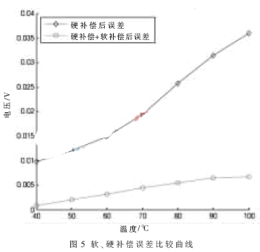
It can be seen from Table 2 that after the soft compensation, the measured values ​​of the seven temperature points are much smaller than the theoretical values. Compared with the hard compensation alone, the error can be reduced to about 1/5, soft, The error curve after hard compensation is shown in Figure 5.
This paper focuses on the method of temperature drift error compensation for high-precision pressure monitoring systems in new special vehicles. Compared with the traditional method, the main feature of this method is the combination of hard compensation and soft compensation. The hard compensation includes the process modulation compensation and amplification circuit compensation of the sensor itself; the soft compensation is performed by embedding the B-spline curve fitting in the MCU for temperature compensation. Compared with other methods, the method is easy to implement, the fitting error is small, the accuracy of the system is greatly improved, and the robustness and stability of the system are improved. The system has been tested in a certain car, with good running condition and high compensation accuracy, and has good promotion and application value.
Anderson Plug Flush Mount,Anderson Plug And Socket,Smh Connector,Anderson Plug,Anderson Connector
Dongguan Andu Electronic Co., Ltd. , https://www.idoconnector.com